35
MOTIF XS6/MOTIF XS7/MOTIF XS8
①
②
Control panel assembly
(コンパネAssy)
Control panel assembly
(コンパネAssy)
Side angle L
(サイドアングルL)
Side angle L
(サイドアングルL)
0〜0.5mm
1
2
• Installing the service stay
(ステイの取り付け方)
G
H
H
1.G のネジ穴にステイの先を通します。
2.サイドアングル L の H 部に、ステイを掛けます。
1. Pass the end of the stay into the threaded hole
marked [G].
2. Make the other end of the stay in engagement
with the portion H of the side angle L.
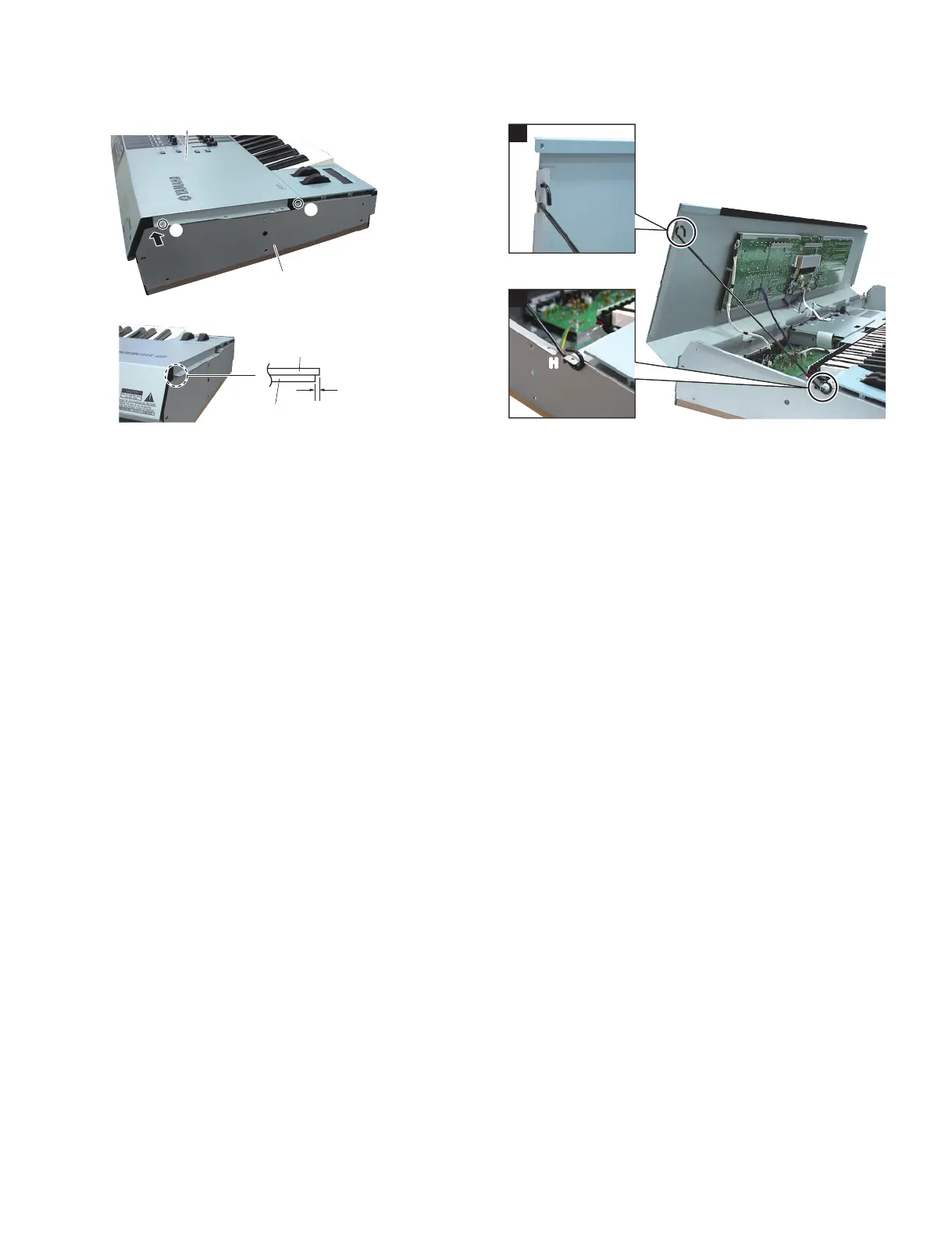
*
When tightening the screws marked [30], tighten the
screws marked q and w in Fig. 1 and Photo 1 fi rst and
then tighten the rest of the screws. When tightening the
screw marked w, tighten the screw while pressing the
portion of the side angle L marked with the arrow in the
direction of the arrow so that the side angle L is placed
behind the control panel assembly. (Fig. 1, Photo 1)
Align the ends of the side cover R and side cover L
with the ends of the control panel assembly.
3. JKAN-JA Circuit Board
(Time required: About 4 minutes)
3-1
Remove the side cover R and side cover L.(See procedure 1.)
3-2 Open the control panel assembly (see procedure 2)
and use the service stay (V6295700) to make the
panel secured. (Photo 2)
3-3
Remove the two (2) screws marked [280], the screw
marked [485] and nine (9) screws marked [290A]. The
JKAN-JA circuit board can then be removed. (Fig. 5)
4. DM Circuit Board
(Time required: About 4 minutes)
4-1
Remove the side cover R and side cover L.(See procedure 1.)
4-2
Open the control panel assembly. (See procedure 3-2.)
4-3 Remove the connector assembly from the cable
clamp on the DM cover.
4-4
Remove the eight (8) screws marked [260A]. The DM
cover and earth plate B can then be removed. (Fig. 5)
4-5 Remove the five (5) screws marked [253A] and
the screw marked [260B]. The DM circuit board
can then be removed. (Fig. 6)
*
If you find extension circuit boards attached to the
CN705 and CN706 when replacing the DM circuit
board, remove the extension circuit boards from the
DM circuit board and then replace the DM circuit board.
* If you replaced the DM circuit board, execute
MAC Address writing. See page 113 for details.
※ [30] のネジを締めるときは、図 1 と写真 1 の①、
②のネジを順に締めてから、残りのネジを締めて
ください。②のネジを締めるとき、サイドアング
ル L の矢印部を矢印の方向に押さえながらネジ締
めし、サイドアングル L がコンパネ Assyの下に
隠れるようにしてください。(図 1、写真 1)
左右側とも、拍子木の端がコンパネ Assyの端に
合うようにします。
3. JKAN-JA シート(所要時間:約 4 分)
3-1 腕木 R と腕木 L を外します。(1 項参照)
3-2 コンパネ Assy を開き(2 項参照)、サービス用の
ステイ(V6295700)でパネルを固定します。(写真 2)
3-3 [280] のネジ 2 本と [485] のネジ 1 本、[290A] のネ
ジ 9 本を外して、JKAN-JA シートを外します。(図 5)
4. DM シート(所要時間:約 4 分)
4-1 腕木 R と腕木 L を外します。(1 項参照)
4-2 コンパネ Assy を開きます。(3-2 項参照)
4-3 カバー DM 上のケーブルクランプから束線を外し
ます。
4-4 [260A] のネジ 8 本を外して、カバー DM とアー
スプレート B を外します。(図 5)
4-5 [253A] のネジ 5 本と [260B] のネジ 1 本を外して、
DM シートを外します。(図 6)
※ DM シートを交換するときに、CN705 と CN706
に拡張基板が差し込まれていれば、DM シートか
ら拡張基板を外してから交換してください。
※ DM シートを交換した場合 MACAddress の書き
込みを行ってください。詳しくは 140 ページを参
照してください。
Photo1( 写真 1) Photo2( 写真 2)

 Loading...