MOTIF XS6/MOTIF XS7/MOTIF XS8
34
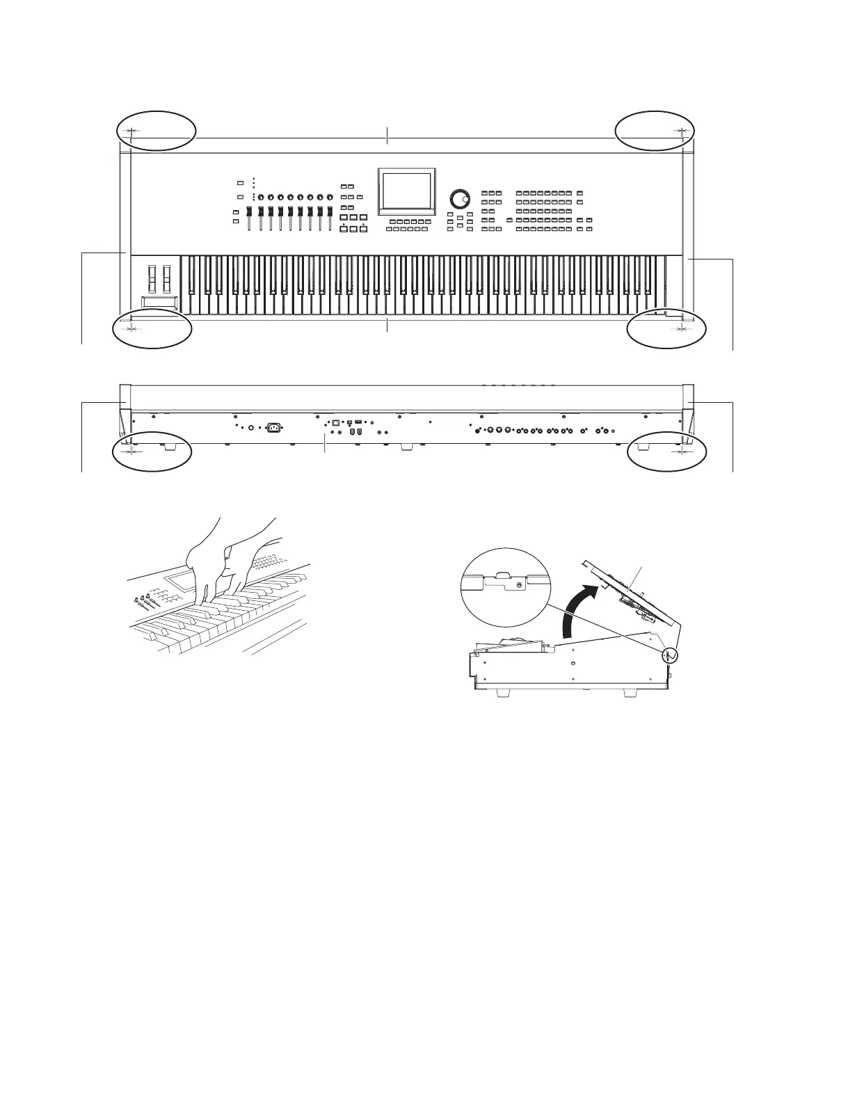
0.5 ± 0.5 mm
1.5 ± 1 mm
0.5 ± 0.5 mm
B A
D C
Side cover R
(腕木R)
Side cover L
(腕木L)
Side cover L
(腕木L)
Side cover R
(腕木R)
Rear panel
(リアパネル)
Front rail assembly
(口棒Assy)
Control panel assembly
(コンパネAssy)
1.5 ± 1 mm
1.5 ± 1 mm
F E
1.5 ± 1 mm
<Top view>
<Rear view>
(3箇所差し込み)
<Right side view>
Control panel assembly
Insert into 3 holes
(コンパネAssy)
2. Control Panel Assembly
(Time required: About 4 minutes)
2-1
Remove the side cover R and side cover L.(See procedure 1.)
2-2 Remove the seven (7) screws marked [30] and
seven (7) screws marked [40A]. (Fig. 1)
2-3 Insert your fi ngers under the middle portion of the
control panel assembly and open to the position
shown in Fig. 4 and then pull off the control panel
assembly upward. (Fig. 3, 4)
* When installing the control panel assembly, tilt
the control panel assembly as shown in Fig. 4
and insert the protrusions from the bottom unit
into the three holes. (Fig. 4)
* When closing the control panel assembly, take
care not to pinch connector assemblies.
2. コンパネ Assy(所要時間:約 4 分)
2-1 腕木 R と腕木 L を外します。(1 項参照)
2-2 [30] のネジ 7 本と [40A] のネジ 7 本を外します。
(図1)
2-3 コンパネ Assy の中央部に指を掛けて図 4 の位置
まで開き、コンパネ Assy を上に引き上げて外し
ます。(図 3、図 4)
※ コンパネ Assy を取り付けるときは、コンパネ
Assy を図 4 のように斜めにして、3 個所の穴に
ボトムユニットから出ている突起を差し込んでく
ださい。(図 4)
※ コンパネ Assy を閉めるときは、束線を挟まない
よう注意してください。
Fig.2( 図 2)
Fig.3( 図 3)
Fig.4( 図 4)

 Loading...