MOTIF XS6/MOTIF XS7/MOTIF XS8
44
• Arm assembly L
(腕木(L)Assy)
<Bottom view>
[L75]
[L75]
[L100]
[L100][L70B]
[L70B]
[L70A]
Side angle L
(サイドアングルL)
Wheel assembly
(ホイールAssy)
End block angle L
(拍子木アングルL)
PNB-RB
[L70A]
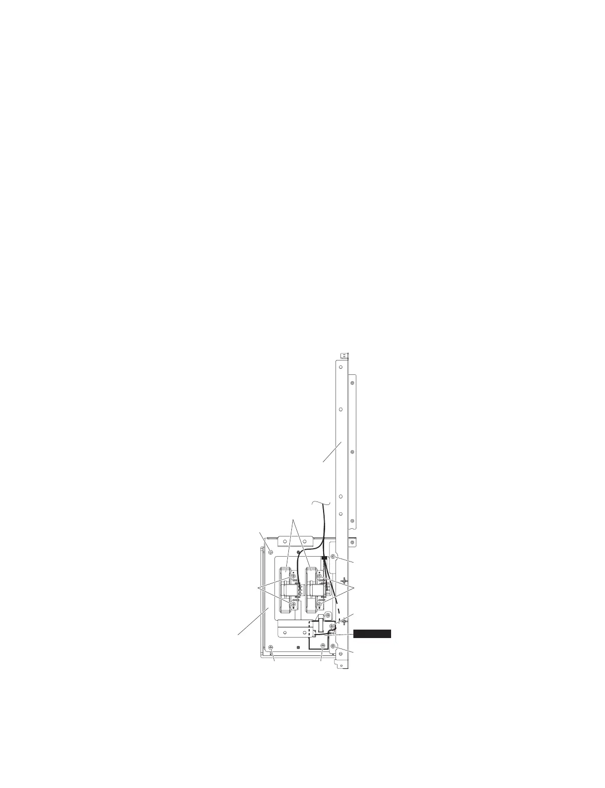
15. Side Angle L, PNB-RB Circuit Board,
Wheel Assembly
(Time required: About 5 minutes each)
15-1 Remove the arm assembly L. (See procedure 14.)
15-2 Side Angle L
15-2-1 Remove the two (2) screws marked [L75]. The
side angle L can then be removed. (Fig. 15)
15-3 PNB-RB Circuit Board
15-3-1
Remove the two (2) screws marked [L100]. The
PNB-RB circuit board can then be removed. (Fig. 15)
15-4 Wheel Assembly
15-4-1 Remove the four (4) screws marked [L70A]. The
wheel assembly can then be removed. (Fig. 15)
16. End Block L, Touch Volume
(Time required: About 6 minutes each)
16-1 Remove the arm assembly L. (See procedure 14.)
16-2 Remove the side angle L and wheel assembly from
the arm assembly L. (See procedure 15-2, 15-4.)
15. サイドアングル L、PNB-RB シート、ホイー
ル Assy
(所要時間:各約 5 分)
15-1 腕木 (L)Assy を外します。(14 項参照)
15-2 サイドアングル L
15-2-1 [L75] のネジ 2 本を外して、サイドアングル L を
外します。(図 15)
15-3 PNB-RB シート
15-3-1 [L100] のネジ 2 本を外して、PNB-RB シートを外
します。(図 15)
15-4 ホイール Assy
15-4-1 [L70A] のネジ 4 本を外して、ホイール Assyを外
します。(図 15)
16. 拍子木 L、タッチボリューム
(所要時間:各約 6 分)
16-1 腕木 (L)Assy を外します。(14 項参照)
16-2 腕木 (L)Assy からサイドアングル L とホイール
Assy を外します。(15-2 項、15-4 項参照)
Fig.15( 図 15)
[L70A],[L70B]: BindHeadTappingScrew-B(B タイト+ BIND)3.0X6MFZN2W3(WE936300)
[L75]: PanHeadScrew(小ネジ+ PAN)5.0X25MFZN2W3(WF001500)
[L100]: BindHeadTappingScrew-B(B タイト+ BIND)3.0X6MFZN2W3(WE936300)

 Loading...