45
MOTIF XS6/MOTIF XS7/MOTIF XS8
(タッチボリューム)
Touch volume
(タッチボリューム)
Touch volume
(拍子木 L)
End block L
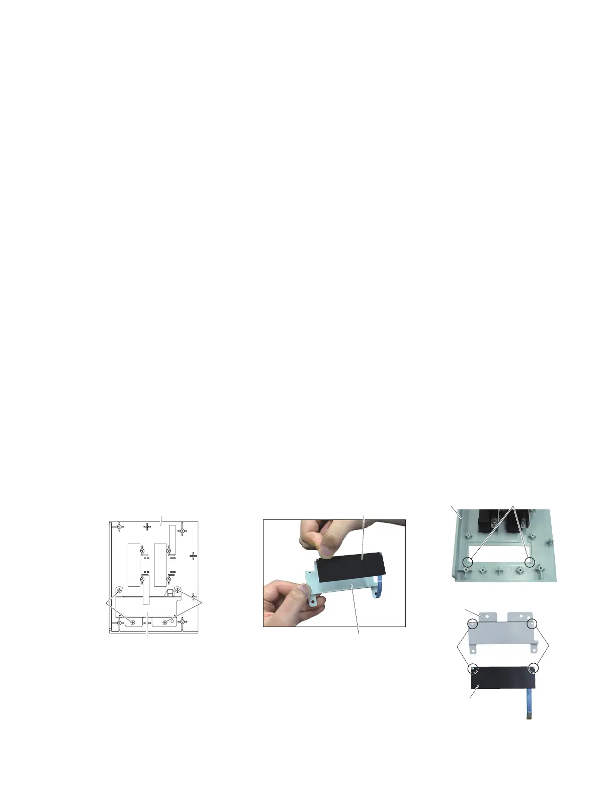
(位置決めピン D)
Positioning pin D
(リボンアングル)
Touch volume angle
(リボンアングル)
Touch volume angle
(ピン穴)
Pin hole
(ピン穴)
Pin hole
[L40]
End block L
(拍子木L)
Touch volume angle
(リボンアングル)
[L40]
16-3 Remove the two (2) screws marked [L70B]. The
end block angle L can then be removed from the
end block L. (Fig. 15)
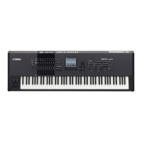
16-4 Remove the four (4) screws marked [L40]. The touch
volume angle can then be removed with the touch
volume attached from the end block L. (Fig. 16)
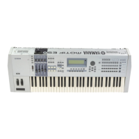
16-5 Separate the touch volume angle from the touch
volume. (Photo 6)
* When installing touch volume, fi t the pin holes
of the touch volume and the pin holes of the
touch volume angle to the positioning pins D
fi rst, and then tighten the screws. (Photo 6)
17. Front Rail Assembly
(Time required: About 8 minutes)
17-1 Turn the unit upside down and remove the two (2)
screws marked [22A], fi ve (5) screws marked [25],
two (2) screws marked [45A], the screw marked
[45B], the screw marked [47], two (2) screws
marked [55A], the screw marked [55B], the screw
marked [57] and the screw marked [58]. (Fig. 12)
17-2 Remove the side covers L and R. (See procedure 1.)
17-3 Remove the control panel assembly.
(See procedure 2.)
17-4 Remove the arm assembly R. (See procedure 12.)
17-5 Remove the arm assembly L. (See procedure 14.)
17-6 Remove the two (2) screws marked [22B]. The
front rail assembly can then be removed by pulling
forward. (Fig. 17)
16-3 [L70B] のネジ 2 本を外して、拍子木 L から拍子木
アングル L を外します。(図 15)
16-4 [L40] のネジ 4 本を外して、拍子木 L からリボン
アングルをタッチボリュームがついた状態で外し
ます。(図 16)
16-5 タッチボリュームとリボンアングルを分離しま
す。(写真 6)
※ タッチボリュームを取り付けるときは、拍子木 L
の位置決めピン D にタッチボリュームのピン穴を
合わせて置き、同じく位置決めピン D にリボンア
ングルのピン穴を合わせて置いてからネジを締め
てください。(写真 6)
17. 口棒 Assy(所要時間:約 8 分)
17-1 本体を裏向きにして、[22A] のネジ 2 本、[25] の
ネジ 5 本、[45A] のネジ 2 本、[45B] のネジ 1 本、[47]
のネジ 1 本、[55A] のネジ 2 本、[55B] のネジ 1 本、
[57] のネジ 1 本、[58] のネジ 1 本を外します。
(図 12)
17-2 腕木 L と腕木 R を外します。(1 項参照)
17-3 コンパネ Assy を外します。(2 項参照)
17-4 腕木 (R)Assy を外します。(12 項参照)
17-5 腕木 (L)Assy を外します。(14 項参照)
17-6 [22B] のネジ 2 本を外して、手前に引くように口
棒 Assy を外します。(図 17)
Fig.16( 図 16)
[L40]:BindHeadTappingScrew-B(B タイト+ BIND)
3.0X6MFZN2W3(WE936300)
Photo6( 写真 6)

 Loading...