47
MOTIF XS6/MOTIF XS7/MOTIF XS8
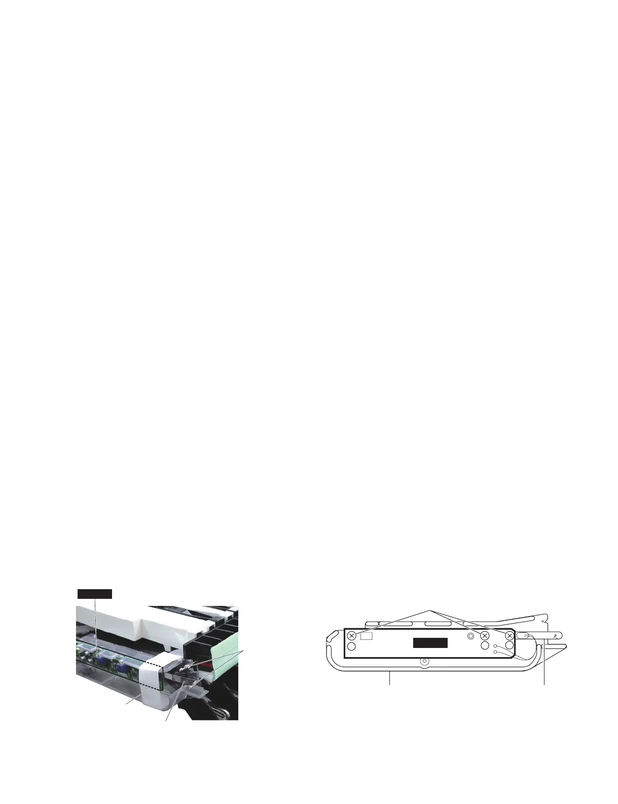
Masking tape
(保護テープ)
PC sensor
(PC センサー)
String
(ストリング)
GHDPC
(PCセンサーバネ)(センサーシートホルダー)
PC sensor spring
GHDPC
Sensor sheet holder
[P60A]
19. Keyboard Assembly
(Time required: About 7 minutes)
* Be sure to hold the side ends of the keyboard
assembly to move it. If the rear side is held, the
string for the PC sensor can be damaged. We
recommend that you cover the GHDPC circuit
board to the right with a tape or the like so that
they may not be mistakenly damaged. (Photo 7)
19-1
Remove the side cover R and side cover L. (See procedure 1.)
19-2
Remove the control panel assembly. (See procedure 2.)
19-3 Remove the arm assembly R. (See procedure 12.)
19-4 Remove the six (6) screws marked [570]. The two
(2) GH covers can then be removed. (Fig. 13)
19-5 Remove the two (2) screws marked [72] and nine
(9) screws marked [75]. Then, while sliding the
keyboard assembly rightward and rearward little
by little, remove it. (Fig. 13)
20. GHDPC Circuit Board
(Time required: About 6 minutes)
20-1
Remove the side cover R and side cover L. (See procedure 1.)
20-2
Remove the control panel assembly. (See procedure 2.)
20-3 Remove the arm assembly R. (See procedure 12.)
20-4 Remove the three (3) screws marked [P60A]. The
GHDPC circuit board can then be removed. (Fig. 20)
21. Exchanging the PC Sensor
21a Prepare a PC Sensor for Replacement
The sensor sheet holder for the PC sensor assem-
bly is fi xed to the keyboard assembly with adhesive
bond and cannot be removed. When replacing the
PC sensor, remove the PC sensor (with a spring)
from the servicing part, PC sensor assembly
(V678290) and use it as a replacement part.
21a-1 Remove the three (3) screws marked [P60] of the
servicing part, PC sensor assembly. (Fig. 20)
21a-2 Remove the GHDPC circuit board and PC sensor
spring from the sensor sheet holder.
19. HEDafEBUS 鍵盤(所要時間:約 7 分)
※ HEDafEBUS 鍵盤を動かすときは、必ず両端を
持ってください。背面を持つと、PC センサーの
ストリングを破損する恐れがあります。
また、右端の GHDPC シートを誤って破損しない
よう、テープなどでマスキングすることを推奨し
ます。(写真 7)
19-1 腕木 R と腕木 L を外します。(1 項参照)
19-2 コンパネ Assy を外します。(2 項参照)
19-3 腕木 (R)Assy を外します。(12 項参照)
19-4 [570] のネジ 6 本を外して、GH カバー 2 個を外し
ます。(図 13)
19-5 [72] の ネ ジ 2 本 と [75] の ネ ジ 9 本 を 外 し て、
HEDafEBUS 鍵盤を右側とリヤ側へ少しずらしな
がら外します。(図 13)
20. GHDPC シート(所要時間:約 6 分)
20-1 腕木 R と腕木 L を外します。(1 項参照)
20-2 コンパネ Assy を外します。(2 項参照)
20-3 腕木 (R)Assy を外します。(12 項参照)
20-4 [P60A] のネジ 3 本を外して、GHDPC シートを外
します。(図 20)
21. PC センサーの交換
21a 交換用PCセンサーの準備
PCセンサーAssyのセンサーシートホルダーは、
接着剤で HEDafEBUS 鍵盤に固定されているた
め、取り外すことが出来ません。
PCセンサーを交換するときは、保守部品のPC セ
ンサーAssy(V678290) からPC センサー( バネ
付き )を取り外し、これを交換用として使用して
ください。
21a-1 保守用のPCセンサーAssy において、[P60]の
ネジ3本を外します。(図 20)
21a-2 センサーシートホルダーから、GHDPCシートと
PCセンサーバネを外します。
Photo7( 写真 7)
Fig.20( 図 20)
[P60A]:BindHeadTappingScrew-P(P タイト+ BIND)
3.0X8MFZN2B3(WF266600)

 Loading...