17
MOTIF XS6/MOTIF XS7/MOTIF XS8
<Bottom view>
<Top view>
<Rear view>
<Right side view>
Side panel R
(サイドパネルR)
Side panel L
(サイドパネルL)
Side panel L
(サイドパネルL)
[40A]
[40C]
[40B]
[40A]
[30A]
[40C]
[40C]
[40C]
[30A]
Side panel R
(サイドパネルR)
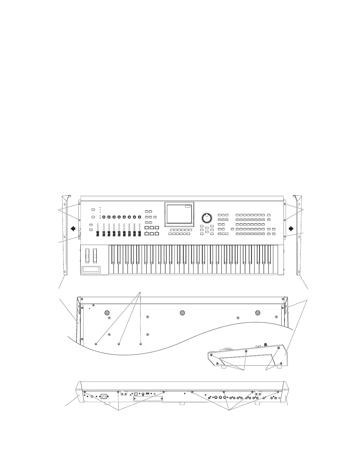
* This fi gure shows the MOTIF XS6.(この図は MOTIFXS6 です。)
1. Side Panel R, Side Panel L
(Time required: About 1 minute each)
1-1 Remove the five (5) screws marked [40A]. The
side panel R can then be removed. (Fig. 1)
* The side panel L can be removed in the same
manner.
2. Control Panel Assembly
(Time required: About 4 minutes)
2-1 Turn the unit upside down and remove the three (3)
screws marked [40B]. (Fig. 1)
2-2 Remove the side panel R and side panel L. (See
procedure 1.)
2-3 Remove the seven (7) screws marked [30A] and
six (6) screws marked [40C]. (Fig. 1)
1. サイドパネル R,サイドパネル L
(所要時間:各約 1 分)
1-1 [40A] のネジ 5 本を外して、サイドパネル R を外
します。(図 1)
※ サイドパネル L も同様にして外すことができます。
2. コンパネ Assy(所要時間:約 4 分)
2-1 本体を裏向きにして、[40B]のネジ3 本を外します。
(図 1)
2-2 サイドパネル R とサイドパネル L を外します。
(1 項参照)
2-3 [30A] のネジ 7 本と [40C] のネジ 6 本を外します。
(図1)
[30A]: BindHeadTappingScrew-B(B タイト+ BIND)4.0X8MFZN2B3(WE962000)
[40A],[40B],[40C]: BindHeadTappingScrew-S(S タイト+ BIND)3.0X8MFZN2B3(WE877800)
Fig.1( 図 1)

 Loading...