39
MOTIF XS6/MOTIF XS7/MOTIF XS8
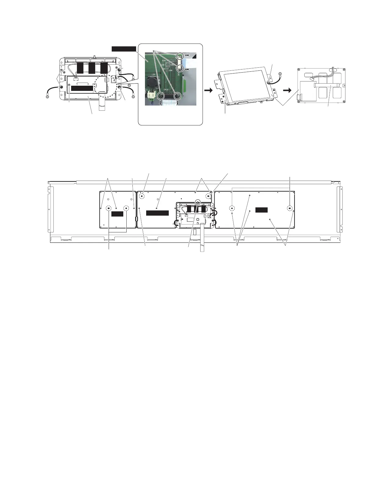
• Display assembly
(ディスプレイAss’y)
<Bottom view>
JKAN-LC
[D80]
[D50]
[D60]
[D60]
[D60]
Claw
CN202
CN203
(ツメ)
Display angle
(ディスプレイアングル)
Display angle
(ディスプレイアングル)
LCD
After the display angle is removed.
(液晶ディスプレイ)
(※ディスプレイアングルを
外した状態)
FFC Cable
(FFCケーブル)
(ツメの部分を矢印の方向に解除し
て、コネクタを外します。)
Remove the connector by releasing
the claws in the direction of the arrow.
JKAN-LC
PNA
PNC
PNB-PN
<Bottom view>
[40C] [40C]
Positioning pin A
[40D]
[40D]
(位置決めピンA)
Positioning pin B
(位置決めピンB)
Positioning pin B
(位置決めピンB)
Positioning pin C
(位置決めピンC)
[90B]
[40D]
[90B]
[I]
9. PNA Circuit Board
(Time required: About 6 minutes)
9-1 Remove the four (4) knobs and five (5) slider
knobs in the portion marked [G]. (Fig. 8)
*
The slider knobs can be attached in the opposite
direction. When attaching the slider knobs, attach
them in the direction as they were before removal.
9-2
Remove the side cover R and side cover L. (See procedure 1.)
9-3
Remove the control panel assembly. (See procedure 2.)
9-4 Remove the two (2) screws marked [410]. The
EMC angle can then be removed. (Fig. 8)
9-5
Remove the two (2) each screws marked [70B]. The
two (2) PCB angles 1 (A) can then be removed. (Fig. 8)
9-6 Remove the three (3) screws marked [40C]. The
PNA circuit board can then be removed. (Fig. 10)
* When installing the PNA circuit board, fit the
holes to the positioning pins A fi rst, and then
tighten the screws. (Fig. 10)
* The PNA circuit board contains the following
buttons. (Photo 3)
• [20]: Push button, MR (Gray) 2 pcs.
• [30]: Push button, M (Gray) 2 pcs.
Fig.9( 図 9)
Fig.10( 図 10)
[D50]:BindHeadTappingScrew-B(B タイト+ BIND)3.0X10MFZN2W3(WE774200)
[D60]:BindHeadTappingScrew-B(B タイト+ BIND)3.0X8MFZN2W3(WE774300)
[D80]:BindHeadTappingScrew-B(B タイト+ BIND)3.0X8MFZN2W3(WE774300)
9. PNA シート(所要時間:約 6 分)
9-1 G 部のノブ 4 個とスライダーノブ 5 個を外します。
(図 8)
※ スライダーノブは向きを逆さにしても取り付けら
れます。スライダーノブを取り付けるときは、元
の向きに取り付けてください。
9-2 腕木 R と腕木 L を外します。(1 項参照)
9-3 コンパネ Assy を外します。(2 項参照)
9-4 [410] のネジ 2 本を外して EMC アングルを外しま
す。(図 8)
9-5 [70B] のネ ジ 2 本 ず つ を 外して、PCB アングル
1(A) を 2 個外します。(図 8)
9-6 [40C] のネジ 3 本を外して、PNA シートを外しま
す。(図 10)
※ PNA シートを取り付けるときは、位置決めピン A
に差し込んでからネジ止めしてください。(図 10)
※ PNA シートには下記のボタンがついています。
(写真 3)
・[20]:プッシュボタン (MR)( 灰 ) 2 個
・[30]:プッシュボタン (M)( 灰 ) 2 個
[40C],[40D]:BindHeadTappingScrew-B(B タイト+ BIND)3.0X6MFZN2W3(WE936300)
[90B]: BindHeadTappingScrew-B(B タイト+ BIND)3.0X6MFZN2W3(WE936300)

 Loading...