23
MOTIF XS6/MOTIF XS7/MOTIF XS8
[10f]: Button, x1 LL W_PLAY (White)
( ボタン (LL),PLAY( 白 ))
[10h]: Button, x1 LL W_STOP (White)
( ボタン (LL),STOP( 白 ))
[10j]: Button, x1 LL W_TOP (White)
( ボタン (LL),TOP( 白 ))
[10b]: Push button, x2 MR (Gray)
( プッシュボタン (MR)( 灰 ))
[10d]: Push button, x3 M (Gray)
( プッシュボタン (M)( 灰 ))
[10e]: Push button, x3 M (Black)
( プッシュボタン (M)( 黒 ))
[10c]: Push button, x1 MR (Gray)
( プッシュボタン (MR)( 灰 ))
[10i]: Button, x1 LL W_FF (White)
( ボタン (LL),FF( 白 ))
[10k]: Button, x1 LL W_REW (White)
( ボタン (LL),REW( 白 ))
[10g]: Button, x1 LL W_REC (White)
( ボタン (LL),REC( 白 ))
• PNB-PN circuit board
(PNB-PN シート)
[20]: Push button, x1 MR (Gray)
( プッシュボタン (MR)( 灰 ))
[30]: Push button, x1 M (Gray)
( プッシュボタン (M)( 灰 ))
• PNA circuit board
(PNA シート)
10. PNB-PN Circuit Board
(Time required: About 6 minutes)
10-1 Remove the four (4) knobs and four (4) slider
knobs in the portion marked [B]. (Fig. 7)
* The slider knobs can be attached in the
opposite direction. When attaching the slider
knobs, attach them in the direction as they
were before removal.
10-2 Remove the side panel R and side panel L.
(See procedure 1.)
10-3 Remove the control panel assembly.
(See procedure 2.)
10-4 Remove the EMC cover. (See procedure 7-3.)
10-5 Remove the two (2) PCB angles 1 (A).
(See procedure 9-4.)
10-6 Remove the shield plate JA. (See procedure 9-5.)
10-7 Remove the screw marked [52B]. The support
angle can then be removed. (Fig. 7)
10-8
Remove the four (4) screws marked [40F]. The
PNB-PN circuit board can then be removed. (Fig. 9)
* When installing the PNB-PN circuit board, fit
the holes to the positioning pins B first, and
then tighten the screws. Also, install with the
claw marked [C] in Fig. 9 positioned above the
circuit board. (Fig. 9)
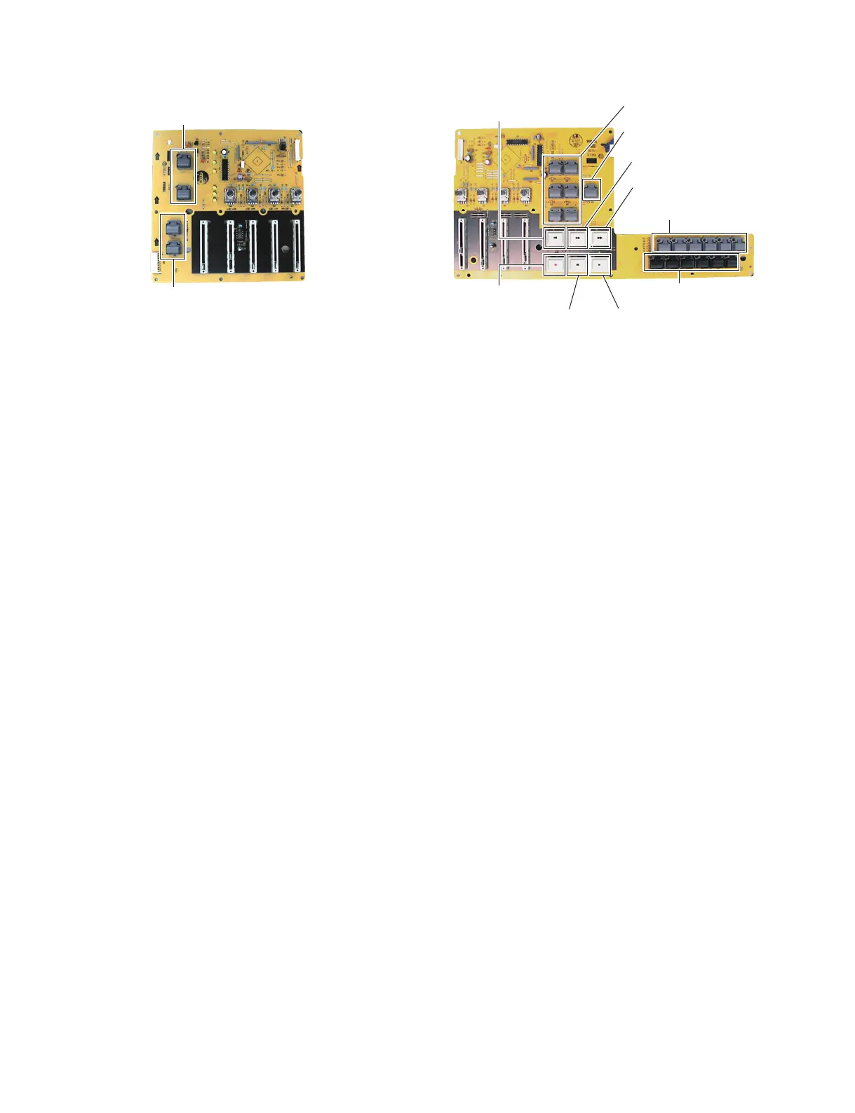
* The PNB-PN circuit board contains the
following buttons. (Photo 4)
• Push button, MR (Gray) 3 pcs.
• Push button, MR (Gray) 1 pc.
• Push button, M (Gray) 2 pcs.
• Push button, M (Black) 2 pcs.
• Button, LL, PLAY (White) 1 pc.
• Button, LL, REC (White) 1 pc.
• Button, LL, STOP (White) 1 pc.
• Button, LL, FF (White) 1 pc.
• Button, LL, TOP (White) 1 pc.
• Button, LL, REW (White) 1 pc.
* The buttons [10f] to [10k] can be attached in
the opposite direction. When attaching the
buttons, attach them in the direction as they
were before removal.
10. PNB-PN シート(所要時間:約 6 分)
10-1 B 部のノブ 4 個とスライダーノブ 4 個を外します。
(図 7)
※ スライダーノブは向きを逆さにしても取り付けら
れます。スライダーノブを取り付けるときは、元
の向きに取り付けてください。
10-2 サイドパネル R とサイドパネル L を外します。
(1 項参照)
10-3 コンパネ Assy を外します。(2 項参照)
10-4 EMC カバーを外します。(7-3 項参照)
10-5 PCB アングル 1(A) を 2 個外します。(9-4 項参照)
10-6 シールド板 JA を外します。(9-5 項参照)
10-7 [52B] のネジ 1 本を外して、サポートアングルを
外します。(図 7)
10-8 [40F] のネジ 4 本を外して、PNB-PN シートを外
します。(図 9)
※ PNB-PN シートを取り付けるときは、位置決めピ
ン B に差し込んでからネジ止めしてください。
また、図 9 で示す [C] のツメがシートの上になる
ようにして取り付けてください。(図 9)
※ PNB-PN シートには下記のボタンがついていま
す。(写真 4)
・[10b]:プッシュボタン (MR)( 灰 ) 3 個
・[10c]:プッシュボタン (MR)( 灰 ) 1 個
・[10d]:プッシュボタン (M)( 灰 ) 2 個
・[10e]:プッシュボタン (M)( 黒 ) 2 個
・[10f]: ボタン (LL),PLAY( 白 ) 1 個
・[10g]:ボタン (LL),REC( 白 ) 1 個
・[10h]:ボタン (LL),STOP( 白 ) 1 個
・[10i]: ボタン (LL),FF( 白 ) 1 個
・[10j]: ボタン (LL),TOP( 白 ) 1 個
・[10k]:ボタン (LL),REW( 白 ) 1 個
※ [10f] 〜 [10k] のボタンは向きを逆さにしても取り
付けられます。ボタンを取り付けるときは、元の
向きに取り付けてください。
Photo3( 写真 3)
Photo4( 写真 4)

 Loading...