MOTIF XS6/MOTIF XS7/MOTIF XS8
20
mLAN support angle
(mLANサポート金具)
[290]
JKAN-ML
[30B]
mLAN cover(mLAN 蓋)
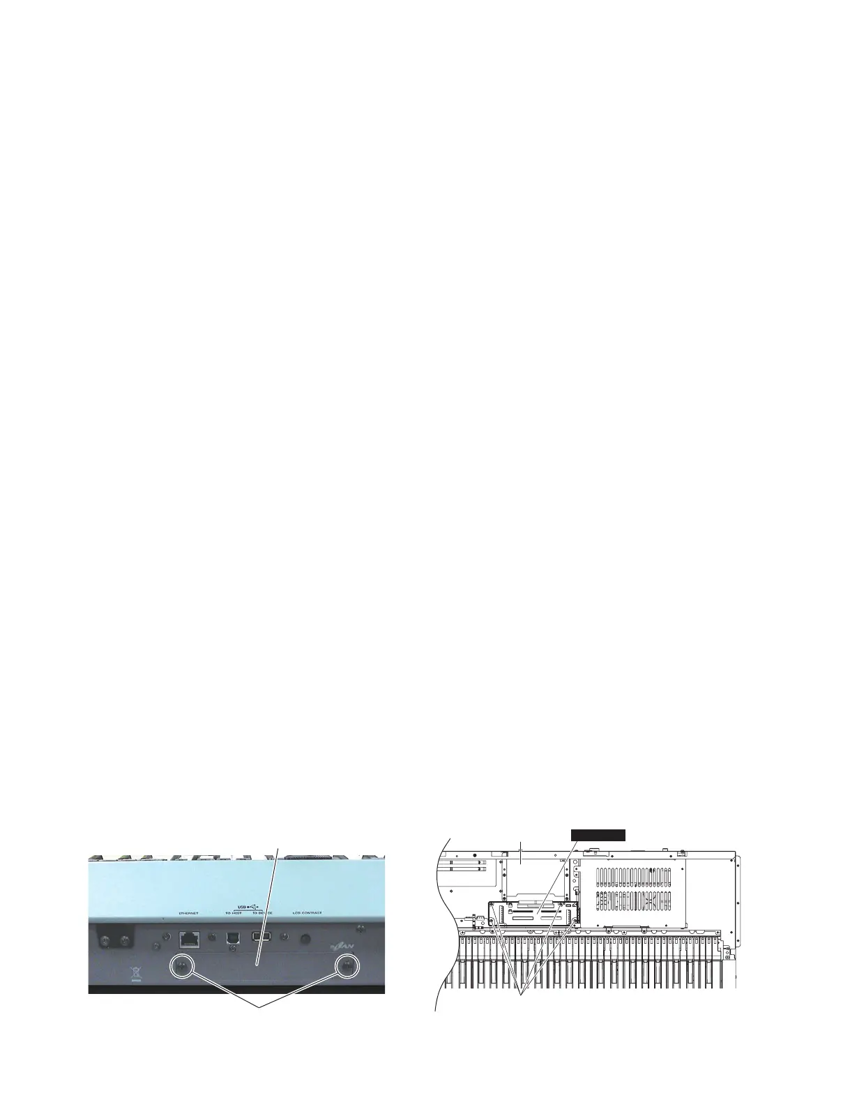
<Rear view>
* This fi gure shows the MOTIF XS7.(この図は MOTIFXS7 です。)
5. JKAN-ML Circuit Board
(Time required: About 6 minutes)
5-1 Remove the side panel R and side panel L.
(See procedure 1.)
5-2 Open the control panel assembly.
(See procedure 3-2.)
5-3 Remove the DM circuit board. (See procedure 4.)
5-4
Remove the four (4) screws marked [290]. The
JKAN-ML circuit board can then be removed. (Fig. 6)
* When installing the JKAN-ML circuit board, fi t
the notch of the mLAN support angle to the
notch of the JKAN-ML circuit board.
* If the mLAN16E2 is inserted, remove the
mLAN16E2 and then remove the JKAN-ML
circuit board.
• Removing the mLAN16E2
a-1 Remove the two (2) screws marked [30B] and
remove the mLAN cover. The mLAN16E2 can
then be removed. (Photo 2)
6.
Power Supply Unit, AC-IN Connector,
Power Switch
(Time required: About 6 minutes)
6-1 Remove the side panel R and side panel L.
(See procedure 1.)
6-2 Open the control panel assembly.
(See procedure 3-2.)
6-3 Remove the screw marked [267] and five (5)
screws marked [270]. The PS guard can then be
removed. (Fig. 4)
6-4
Power Supply Unit (Time required: About 6 minutes)
6-4-1 Remove the five (5) screws marked [230]. The
power supply unit can then be removed. (Fig. 5)
6-5 AC-IN Connector, Power Switch
(Time required: About 5 minutes)
6-5-1 Remove the four (4) screws marked [200] and
the screw marked [210]. The AC IN connector
assembly can then be removed. (Fig. 5)
6-5-2 Remove the AC-IN connector from the AC IN
connector assembly. (Fig. 5)
6-5-3 Remove the two (2) screws marked [190] and
remove the power switch holder from the AC IN
connector assembly. The power switch can then
be removed. (Fig. 5)
5. JKAN-ML シート(所要時間:約 6 分)
5-1 サイドパネル R とサイドパネル L を外します。
(1 項参照)
5-2 コンパネ Assy を開きます。(3-2 項参照)
5-3 DM シートを外します。(4 項参照)
5-4 [290] のネジ 4 本を外して、JKAN-ML シートを外
します。(図 6)
※ JKAN-ML シートを取り付けるときは、mLAN サ
ポート金具の切りかきと JKAN-ML シートの切り
かきをはめ合わせて取り付けてください。
※ mLAN16E2 が挿入されている場合は、mLAN16E2
を取り外してから JKAN-ML シートを外してくだ
さい。
•mLAN16E2 の外し方
a-1 [30B] の ネ ジ 2 本 を 外 し て mLAN 蓋 を 外 し、
mLAN16E2 を取り外します。(写真 2)
6. 電源ユニット、AC インレット、
電源スイッチ
(所要時間:約 6 分)
6-1 サイドパネル R とサイドパネル L を外します。
(1 項参照)
6-2 コンパネ Assy を開きます。(3-2 項参照)
6-3 [267] のネジ 1 本と [270] のネジ 5 本を外してガー
ド PS を外します。(図 4)
6-4 電源ユニット(所要時間:約 6 分)
6-4-1 [230] のネジ 5 本を外して、電源ユニットを外し
ます。(図 5)
6-5 AC インレット、電源スイッチ(所要時間:約 5 分)
6-5-1 [200] の ネ ジ 4 本 と [210] の ネ ジ 1 本を外して、
ACIN 束線を外します。(図 5)
6-5-2 ACIN 束線から AC インレットを外します。(図 5)
6-5-3 [190] のネジ 2 本を外して、ACIN 束線から PSW
アングルを外してから、電源スイッチを外します。
(図5)
Fig.6( 図 6)
[290]:BindHeadTappingScrew-B(B タイト+ BIND)
3.0X6MFZN2W3(WE936300)
Photo2( 写真 2)
[30B]:BindHeadScrew(小ネジ+ BIND)4.0X6MFZN2B3(WE878400)

 Loading...