51
MOTIF XS6/MOTIF XS7/MOTIF XS8
Master strings
(マスターストリング)
V-spring assembly
(VバネAssy)
PC sensor spring
(PCセンサーバネ)
Slave strings
(スレーブストリング)
Adhesive tape
(両面テープ)
SLIT
PC sensor spring
(PCセンサーバネ)
Slave strings
(スレーブストリング)
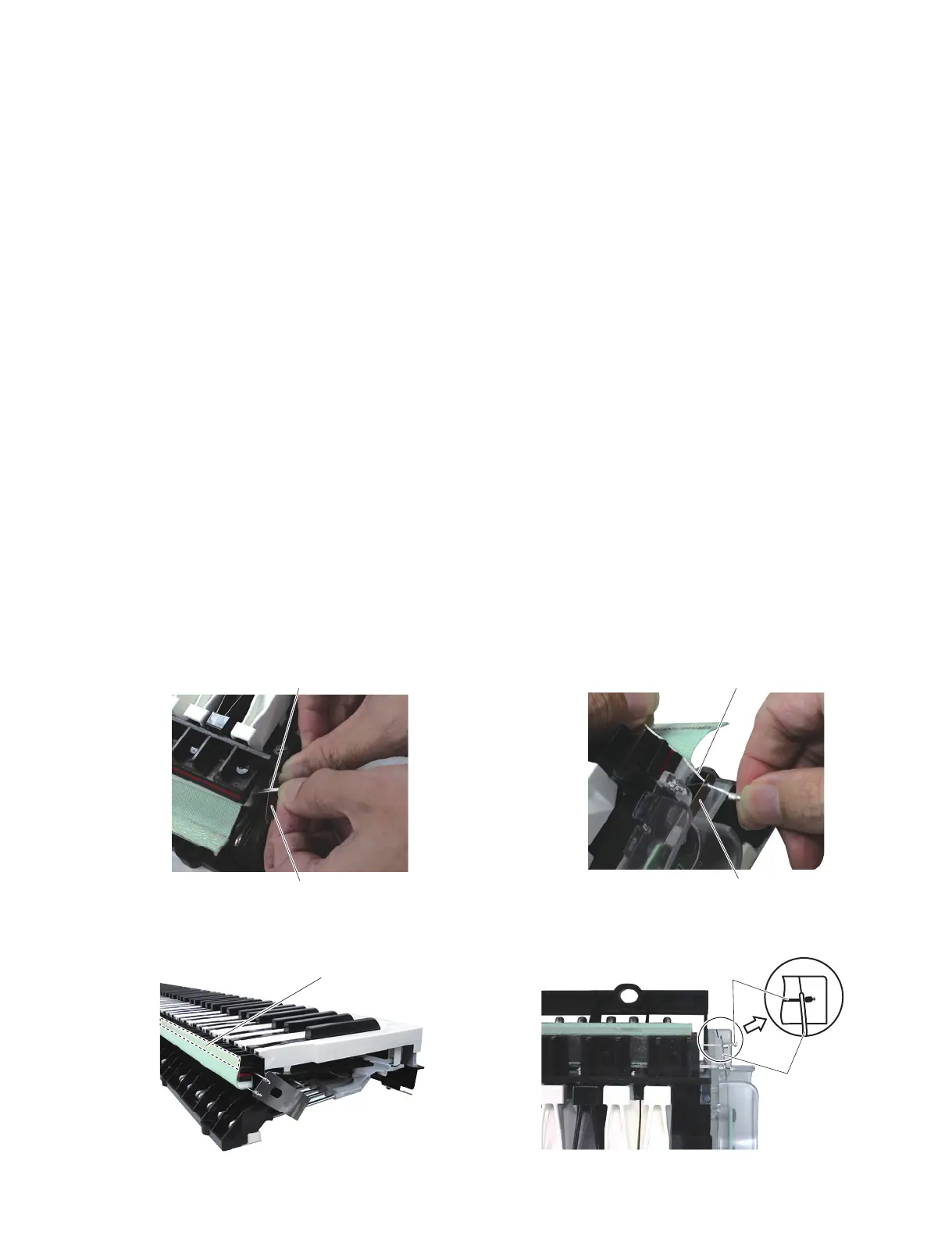
22b-2 Untwist the master strings fully and insert them
into the slit of the V-spring assembly. (Photo 14)
After insertion, check that the V-spring assembly can
be moved smoothly in the direction of the strings.
Check also that the master strings can be seen from
the clearance between the frame and the stopper.
22b-3 Insert the slave strings into the slit of the V-spring
assembly. (Photo 8, Photo 9)
22b-4 Untwist the slave strings fully and insert them into
the slit of the PC sensor spring. (Photo 15)
After insertion, check that the PC sensor spring
can be moved smoothly in the direction of the
strings. Check also that the slave strings do not
come off the stopper and that they are positioned
at the center of the stopper.
22b-5 Attach the two-sided tape that comes with the
string set to the frame side and attach the cloth
cover. (Photo 16)
22b-6 Check that the position of the PC sensor spring is
at the marking portion of the sensor sheet holder.
(Photo 17)
* The position of the sensor is detected automati-
cally. Maximum tolerance is 0.5 mm forward or
backward.
* After the servicing, press the key and check that
the PC sensor spring can be moved.
22b-2 マスターストリングの撚りを十分に戻し、V バネ
Assy のスリットに挿入します。(写真 14)
挿入後、V バネ Assy がストリングの方向に沿っ
てスムーズに動くことを確認します。
また、マスターストリングがフレームとストッ
パーの間から見えることを確認します。
22b-3 スレーブストリングを V バネ Assy のスリットに
挿入します。(写真 8、写真 9)
22b-4 スレーブストリングの撚りを十分に戻し、PC セ
ンサーバネのスリットに挿入します。(写真 15)
挿入後、PC センサーバネがストリングの方向に
沿ってスムーズに動くことを確認します。
また、スレーブストリングがストッパーから脱落
することなく、ストッパーの中心に位置している
ことを確認します。
22b-5 ストリングセット付属の両面テープをフレーム側
に貼り、布カバーを取り付けます。(写真 16)
22b-6 PC センサーバネの位置が、センサーシートホル
ダーのマーキング部分に重なっていることを確認
します。(写真 17)
※ センサーの位置は自動検出されます。許容誤差は、
前後 0.5mm 以内です。
※ 作業終了後、鍵盤を押してPCセンサーバネが動
くことを確認してください。
Photo14( 写真 14) Photo15( 写真 15)
Photo16( 写真 16) Photo17( 写真 17)

 Loading...