SERVO SELECTION AND DATA SHEETS
5.4.1 Servomotor Dimensional Drawings
278
4) The quoted allowable radial load is the value at a position 35 mm (1.38 in.) from the mo-
tor mounting surface.
5) The electromagnetic brake is only to hold the load in position and cannot be used to stop
the motor.
6) Conforms to IP55 protective structure (except connector and output shaft faces).
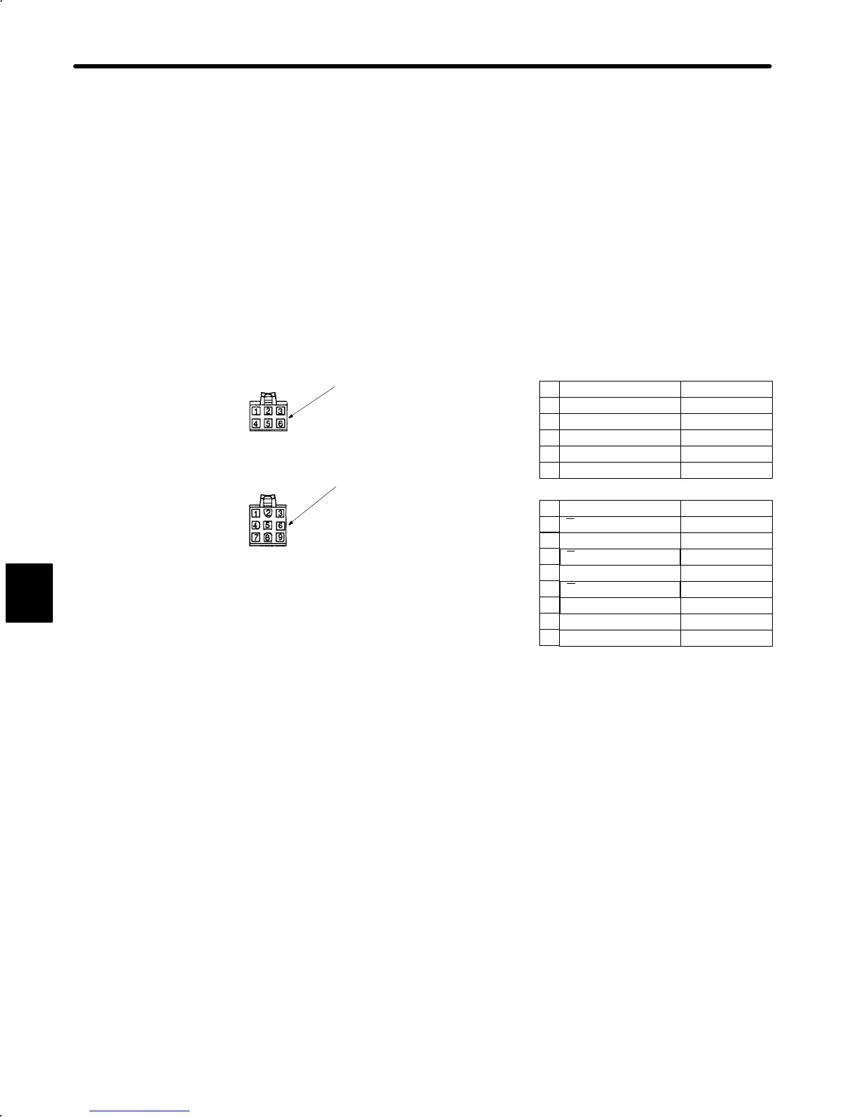
• Details of Motor and Encoder Plugs (Common for 100 W (0.13 HP) to 750 W (1.01 HP))
Socket 170362-1 or 170366-1
U phase Red
V phase White
W phase Blue
FG Green/Yellow
Pin 170360-1 or 170364-1
Cap 172160-1
Motor Wiring Specifications
Incremental Encoder Wiring Specifications
A channel output Blue
A channel output Blue/Black
B channel output Yellow
Yellow/Black
Green
Green/Black
Gray
Red
FG (Frame Ground) Orange
Plug: 172169-1 (AMP)
Pin: 170359-1 or 170366-1
Plug : 172168-1 (AMP)
Connected to
Connected to
Cap :172161-1
Socket: 170361-1 or 170365-1
1
2
3
4
1
2
3
5
6
7
8
9
Brake Black
Brake Black
5
6
B channel output
4
C channel output
C channel output
0V (power supply)
+5V (power supply)
Motor Plug
Encoder Plug
5
cont.
 Loading...


