5.6Specifications and Dimensional Drawings of Peripheral Devices
317
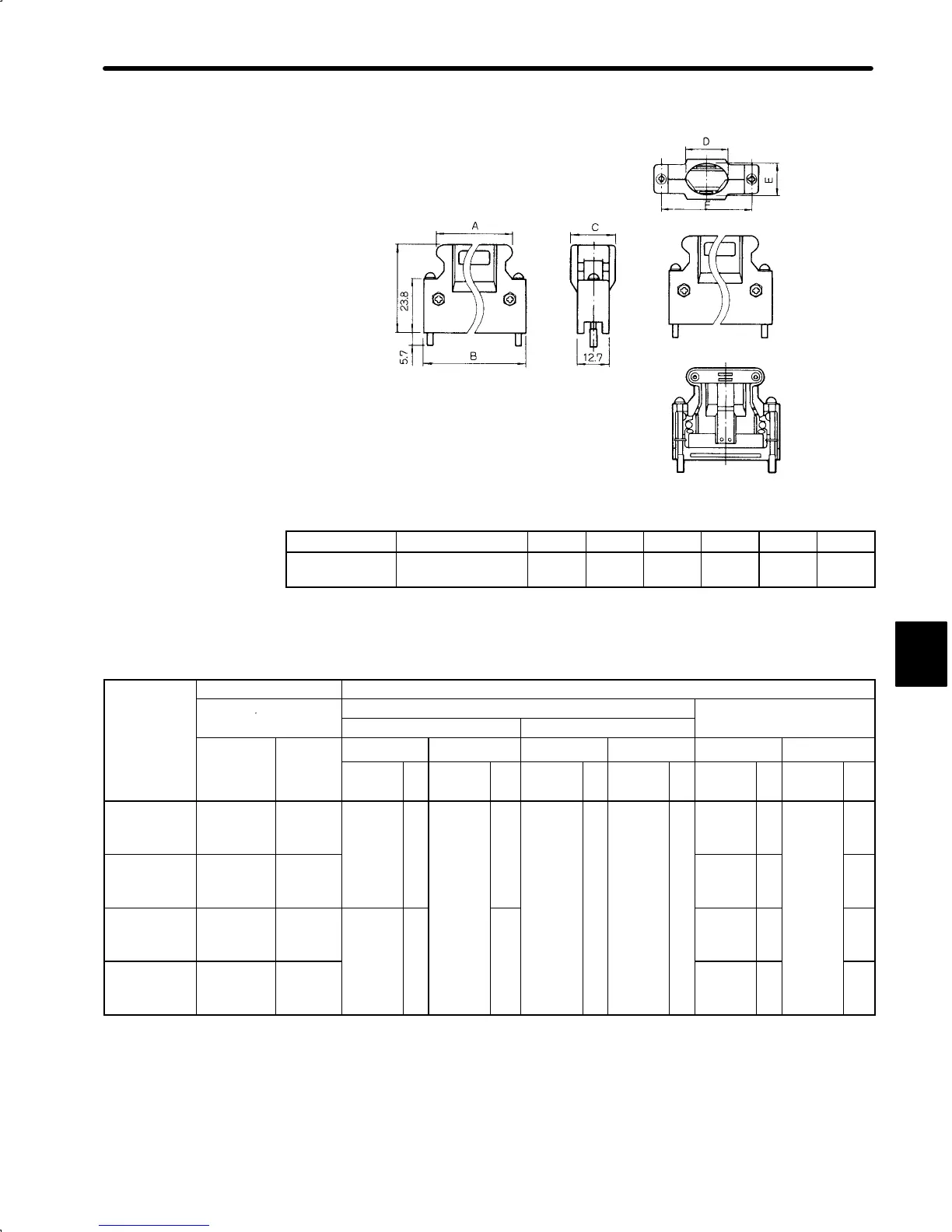
• Case
For -52A0
Diagram of Assembled Connector (for reference)
(0.22)
(0.94)
(0.5)
Units: mm (inches)
Connector Case A B C D E F
10120-3000VE 10320-52A0-008 22.0
(0.87)
18.0
(0.71)
14.0
(0.55)
12.0
(0.47)
10.0
(0.39)
27.4
(1.08)
5) The types of connector kit are shown below. Select the type of connector kit according to
the connectors selected in (2), (3), and (4) above.
Connector
Application Connector Kit Part List
Kit Type
Encoder/Motor Cable
For Encoder Cable
For Motor Cable
Encoder End Servopack End
Encoder
Motor
Cap Socket Connector Case Cap Socket
Type Brake
With/
Without
Type Q
ty
Type Qt
y
Type Q
ty
Type Q
ty
Type Q
ty
Type Qt
y
DP9420006-1 Incremental Without
*1
172161
-1
1 *1
170365
-1
*3
10
*2
10120-
3000VE
1 *2
10320-
52A0-
1
*1
172159
-1
1
*1
170366
-1
*3
5
DP9420006-2 Incremental With
008
*1
172160
-1
1 *3
7
DP9420006-3 Absolute Without
*1
172163
-1
1 *3
16
*1
172159
-1
1 *3
5
DP9420006-4 Absolute With *1
172160
-1
1 *3
7
*1 Manufactured by AMP.
*2 Manufactured by 3M.
*3 Including one spare.
5
 Loading...


