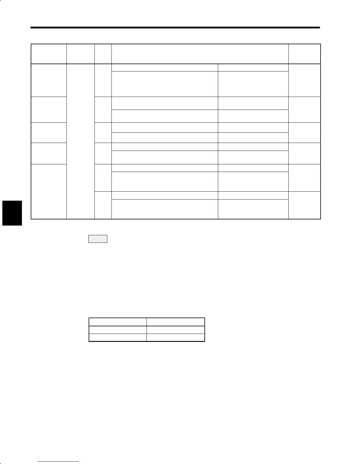
LIST OF USER CONSTANTS
410
User
Constant
No.
Bit
No.
Setting Factory
Setting
Error counter
Cn-02 A
0 1
0
clear signal
Clears the error counter when an error
counter clear signal is at high level.
Clears the error counter
when the leading edge of an
error counter clear signal
rises.
Integration
time
B
0 1
0
constant
setting unit
1ms 0.01 ms
Torque
C
0 1
0
re
erence
filter
Primary Secondary
Reference
D
0 1
0
pulse logic
Does not invert reference pulse logic. Inverts reference pulse
logic.
Others E
0 1
0
Displays position error Un-08 in x 1
reference units while in monitor mode.
Displays position error
Un-08 in x 100 reference
units while in monitor mode.
F
0 1
0
Line driver
(Maximum reference pulse frequency: 450
kpps)
Open collector
(Maximum reference pulse
frequency: 200 kpps)
: User constants that must be always set
NOTE For the Cn-01 and Cn-02 memory switches, always turn the power OFF and then ON after
changing the setting. This makes the new setting valid.
Note 1) Internal speed selection is valid only when bit 2 of Cn-02 is set to “1.”
2) The factory setting depends on the Servopack type as shown below.
Servopack Type Factory Setting
SGDA-jjjP
0
SGDA-jjjPP
1
D
 Loading...


