BASIC USES OF Σ-SERIES PRODUCTS
2.4.2 Step 1: Conducting a Test Run for Motor without Loadcont.
42
(2) Turn the servo ON signal ON.
Set S-ON (1CN-14) to 0 V. If normal, the motor
is turned ON and the Digital Operator displays
the data as shown in the figure. If an alarm dis-
play appears, take appropriate action as de-
scribed in Appendix E List of Alarm Displays.
(9) Operate by reference input.
The operating procedure differs according to the Servopack control mode used.
Servopack for Speed/Torque
(This section describes the standard speed con-
trol setting.)
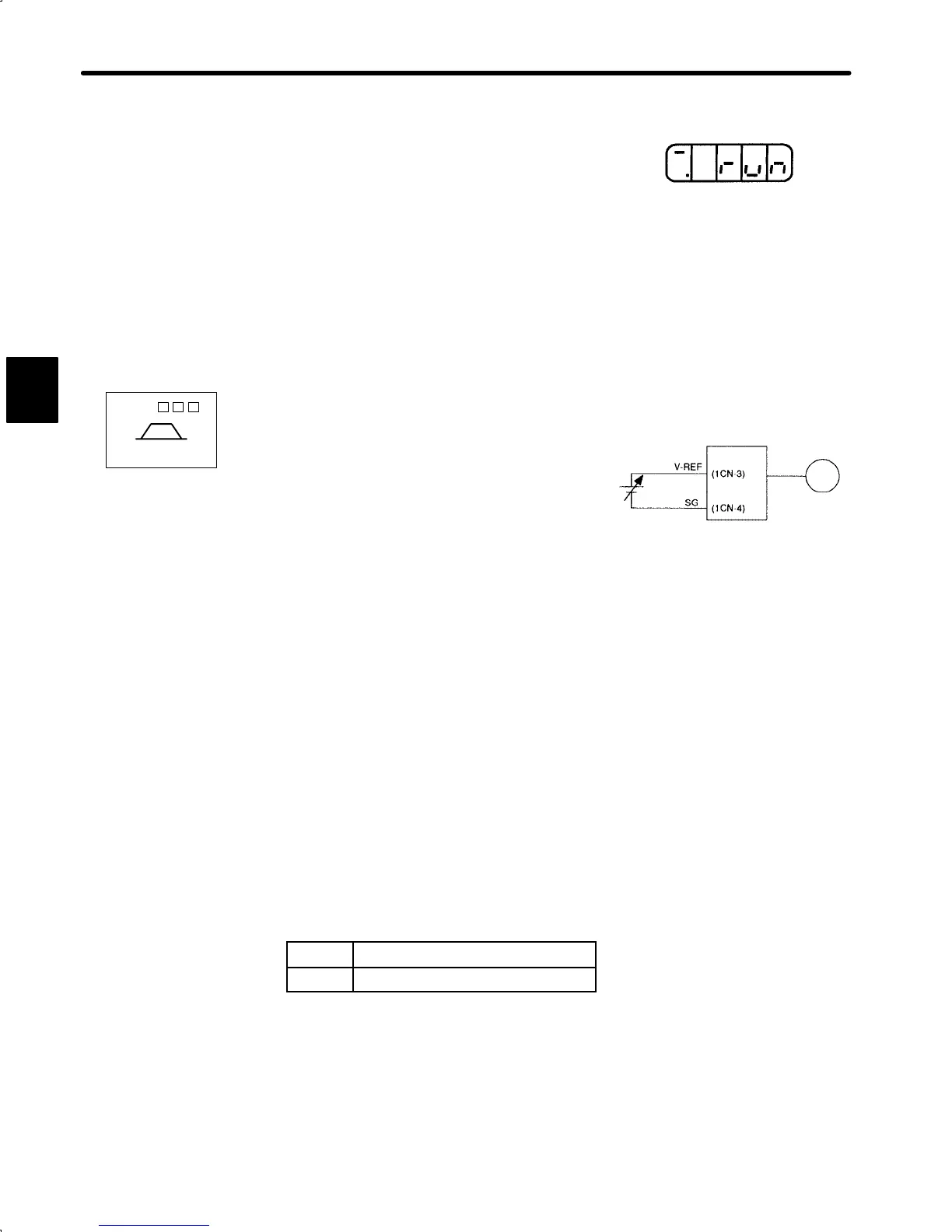
(1) Gradually increase the speed reference input
(V-REF, 1CN-3) voltage. The motor will rotate.
When a host controller such as a programmable controller performs position
control, it may be difficult to directly input the speed reference voltage. In this
case, constant voltage reference should be input once to ensure correct opera-
tion.
(2) Check the following items in monitor mode (see page 179):
(1) Has a reference speed been input?
(2) Is the motor speed as set?
(3) Does the reference speed match the actual motor speed?
(4) Does the motor stop when no reference is input?
Un-00
Actual motor speed
Un-01 Reference speed
(3) If the motor rotates at an extremely slow speed when 0 V is specified as the reference
voltage, correct the reference offset value as described in Section 4.2.4 Reference
Offset Automatic Adjustment
2
Display when servo is turned ON
SGDA- S
Speed/Torque
Servopack
Servomotor
Servomotor rotates at a speed
proportional to the reference voltage.
 Loading...


