APPLICATIONS OF Σ-SERIES PRODUCTS
3.2.3 Using Encoder Outputcont.
74
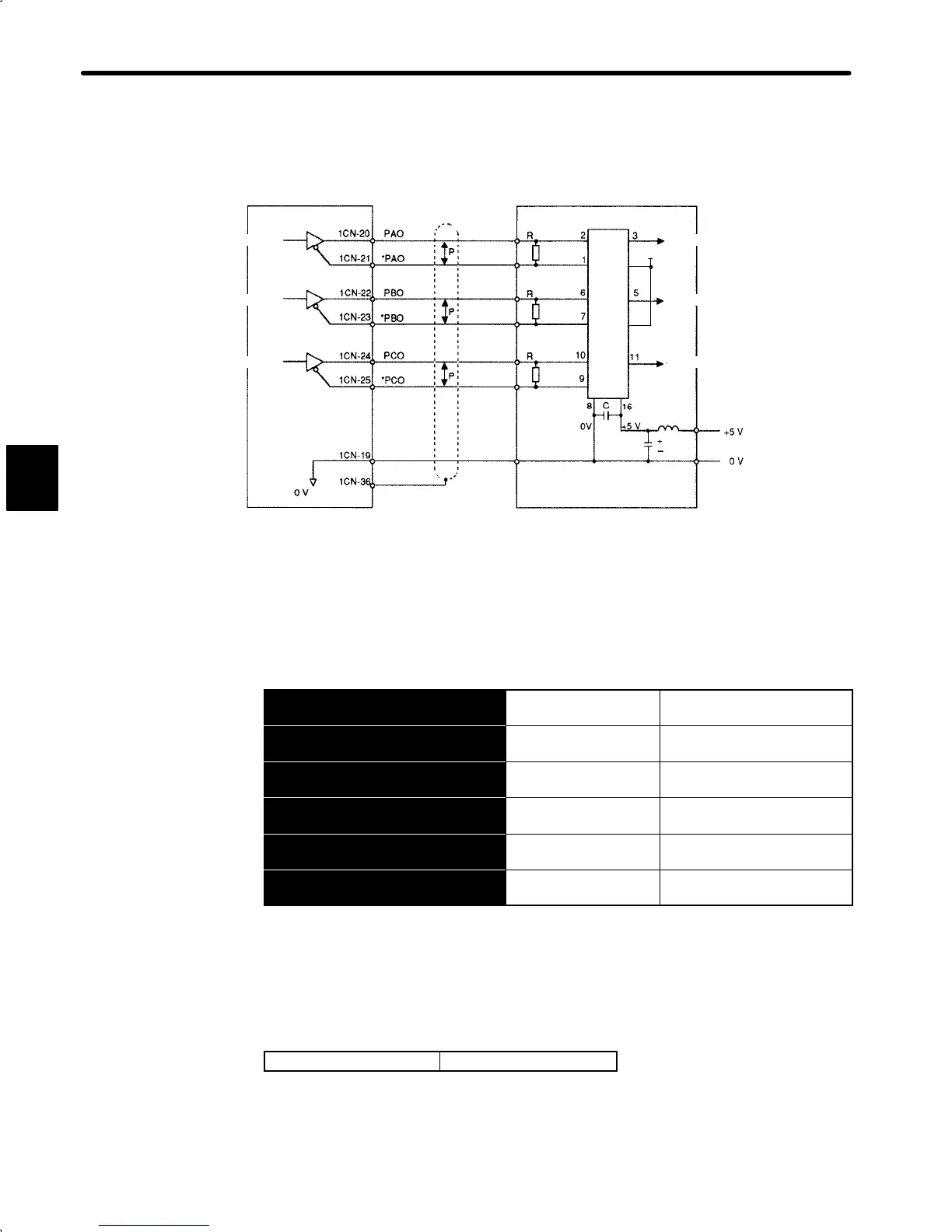
The output circuit is for line driver output. Connect each signal line according to the fol-
lowing circuit diagram.
4
Servopack
Host controller
Line receiver
Choke
coil
Smoothing
capacitor
Line receiver used: SN75175 manufactured by
Texas Instruments Inc. or
MC3486 (or equivalent)
R (termination resistor): 220 to 470 Ω
C (decoupling capacitor): 0.1 μF
↕P: Represents twisted-pair cables
Phase A
Phase B
Phase C
Phase A
Phase B
Phase C
12
+5V
2) I/O signals are described below.
Output → PAO 1CN-20
Encoder Output
Phase-A
For Speed/Torque Control
and Position Control
Output →
£
PAO 1CN-21
Encoder Output
Phase-A
For Speed/Torque Control
and Position Control
Output → PBO 1CN-22
Encoder Output
Phase-B
For Speed/Torque Control
and Position Control
Output →
£
PBO 1CN-23
Encoder Output
Phase-B
For Speed/Torque Control
and Position Control
Output → PCO 1CN-24
Encoder Output
Phase-C
For Speed/Torque Control
and Position Control
Output →
£
PCO 1CN-25
Encoder Output
Phase-C
For Speed/Torque Control
and Position Control
Divided encoder signals are output.
Always connect these signal terminals when a position loop is formed in the host control-
ler to perform position control.
Set a dividing ratio in the following user constant.
Dividing ratio setting
Cn-0A PGRAT
The dividing ratio setting is not relevant to the gear ratio setting (Cn-24, 25) for the
electronic gear function of the Servopack for position control (SGDA-jjjP).
3
 Loading...


