3.2Setting User Constants According to Host Controller
75
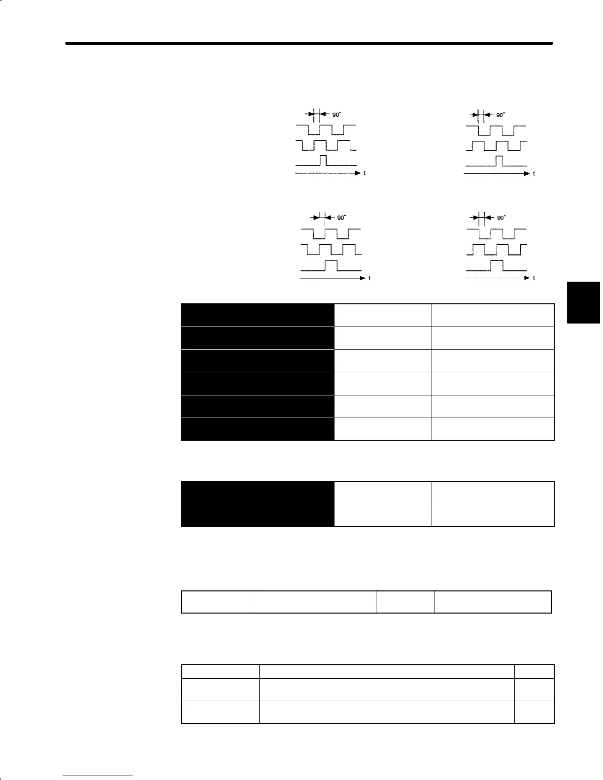
Output Phase Form
Forward rotation Reverse rotation
Incremental Encoder
Phase A
Phase B
Phase C
Phase A
Phase B
Phase C
Absolute Encoder
Forward rotation Reverse rotation
Phase A
Phase B
Phase C
Phase A
Phase B
Phase C
→ Input SEN 1CN-5
SEN Signal Input For Speed/Torque Control
Only
→ Input 0SEN 1CN-6
SEN Signal Input For Speed/Torque Control
Only
Output → PSO 1CN-26
Encoder Output
Phase-S
For Speed/Torque Control
and Position Control
Output →
£
PSO 1CN-27
Encoder Output
Phase-S
For Speed/Torque Control
and Position Control
→ Input BAT 1CN-28
Battery (+) For Speed/Torque Control
and Position Control
→ Input BAT0 1CN-29
Battery (−) For Speed/Torque Control
and Position Control
Use these signals (SEN to BAT0) for absolute encoders. For details, refer to 3.8.5 Using
an Absolute Encoder.
Output → SG 1CN-19
Signal Ground for
Encoder Output
For Speed/Torque Control
and Position Control
Output → FG 1CN-36
Frame Ground For Speed/Torque Control
and Position Control
SG: Connect to 0 V on the host controller.
FG: Connect to the cable shielded wire.
3) Use the following memory switch to specify the type of the encoder to be used.
Cn-01 Bit E
Encoder Type Selection Factory
Setting: 0
For Speed/Torque Control
and Position Control
Sets the encoder type according to the servomotor type as shown in the table.
After changing the memory switch setting, always turn the power OFF, then ON.
Motor Type Number of Encoder Pulses Per Revolution (P/R) Setting
SGM-jjj31j
Incremental encoder:
2,048 pulses per revolution
0
SGM-jjjW1j
Absolute encoder:
1,024 pulses per revolution
1
3
 Loading...


