6.1 Adjustments and Basic Adjustment Procedure
6-7
∗ When using an SGMCS direct-drive servomotor, the motor speed will be automatically set to 1 V/100 min
-1
.
(2) Setting Monitor Factor
The output voltages on analog monitor 1 and 2 are calculated by the following equations.
(3) Related Parameters
Use the following parameters to change the monitor factor and the offset.
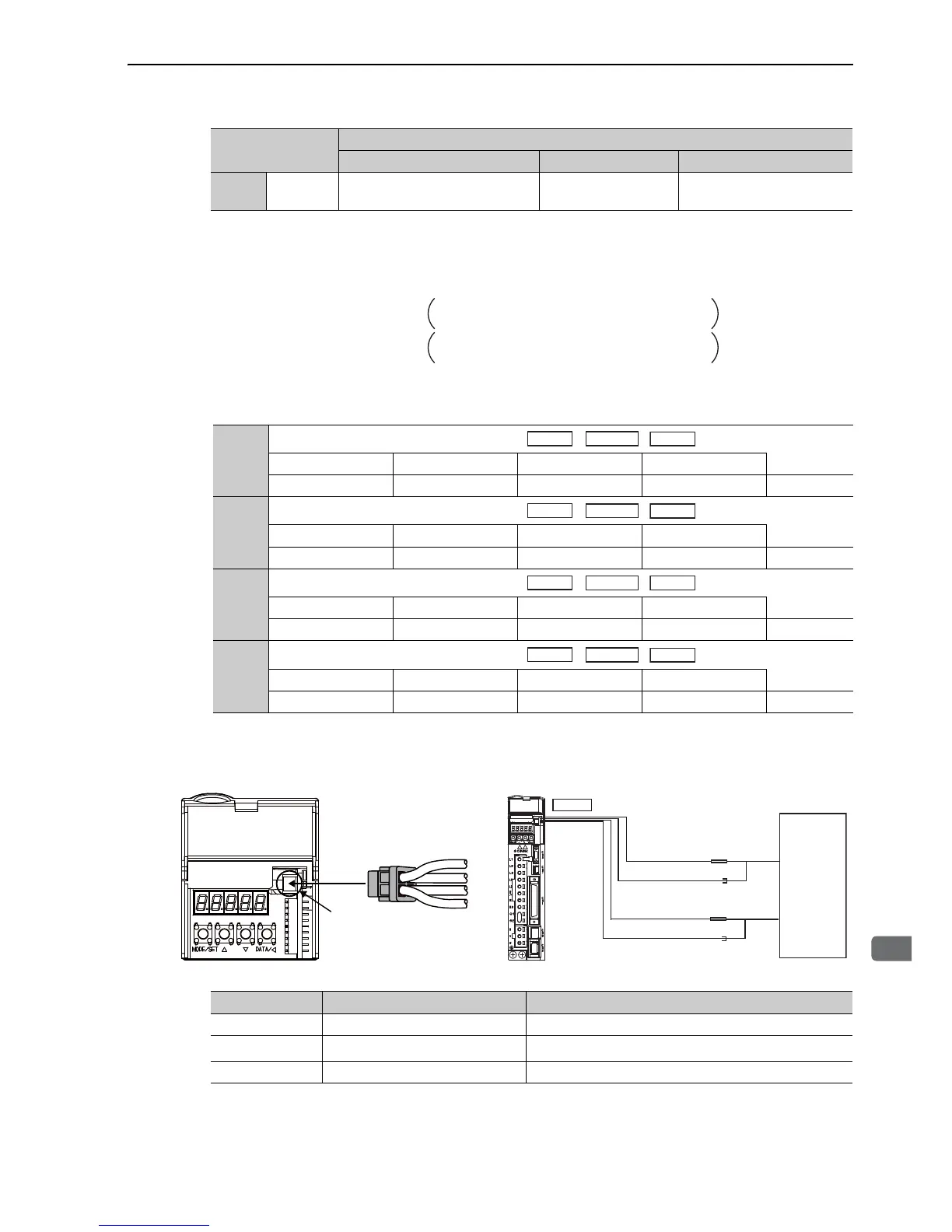
(4) Connector CN5 for Analog Monitor
To monitor analog signals, connect a measuring instrument with cable (JZSP-CA01-E) to the connector CN5.
∗ When using an SGMCS direct-drive servomotor, the motor speed will be automatically set to 1 V/100 min
-1
.
Pn006
Pn007
n.0D External encoder speed
1 V/1000 min
-1
Value at motor shaft
Parameter
Description
Monitor Signal Measurement Gain Remarks
Analog monitor 1 output voltage = (-1) × Signal selection
(Pn006=n.00غغ)
(Pn552)
Analog monitor 2 output voltage = (-1)
× Signal selection
(Pn007=n.00غغ)
× Multiplier + Offset voltage [V]
× Multiplier + Offset voltage [V]
(Pn550)
(Pn551)
(Pn553)
Pn550
Analog Monitor 1 Offset Voltage
Classification
Setting Range Setting Unit Factory Setting When Enabled
-10000 to 10000 0.1 V 0 Immediately Setup
Pn551
Analog Monitor 2 Offset Voltage
Classification
Setting Range Setting Unit Factory Setting When Enabled
-10000 to 10000 0.1 V 0 Immediately Setup
Pn552
Analog Monitor 1 Magnification
Classification
Setting Range Setting Unit Factory Setting When Enabled
-10000 to 10000 0.01 times 100 Immediately Setup
Pn553
Analog Monitor 2 Magnification
Classification
Setting Range Setting Unit Factory Setting When Enabled
-10000 to 10000 0.01 times 100 Immediately Setup
Speed
Position
Line Color Signal Name Factory Setting
White Analog monitor 1 Torque reference: 1 V/100% rated torque
Red Analog monitor 2
Motor speed: 1 V/1000 min
-1 *
Black (2 lines) GND Analog monitor GND: 0 V
Probe
GND
Probe
GND
Measuring
Probe
Measuring
Probe
Measuring
Instrument
*
White
Red
Black
Black
CN5
CN5
JZSP-CA01-E
White
Red
Black
Black
Connection Example
∗Measuring instrument is not included.