5-1
IM DL850-03EN
External Signal I/O
5.1 External Trigger Input (TRIGGER IN)
CAUTION
Only apply signals that meet the following specifications. Signals that do not meet the
specifications may damage the DL850/DL850V, because of factors such as excessive voltage.
External Trigger Input Terminal
This terminal is used when an external signal is used as the trigger source.
Item Specifications
Connector type BNC
Input level TTL (0 to 5 V)
Minimum pulse width 100 ns
Logic Rising and falling edges
Trigger delay time Within 100 ns + 1 sample period
Externally synchronized operation Possible (through the connection of the TRIG IN and TRIG OUT
terminals of two DL850/DL850Vs)
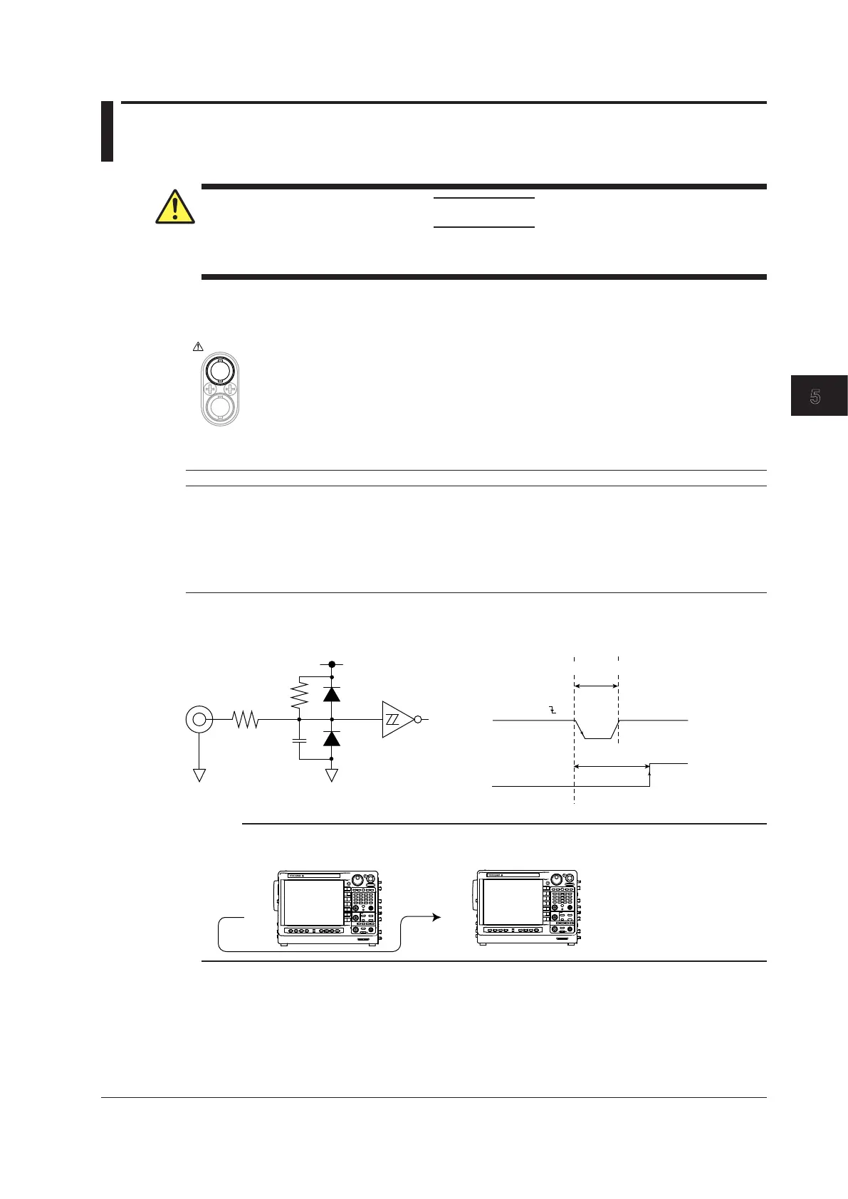
Circuit Diagram and Timing Chart for External Trigger Input
Equivalent
to LCX14
100 Ω
4.7 kΩ
100 pF
+5 V
Minimum pulse width
Trigger delay time
TRIG IN
(When set to )
Internal trigger
Note
You can synchronize the operation of two DL850/DL850Vs by using the trigger output function.
TRIG
OUT
No. 1
TRIG
IN
No. 2
DL850/
DL850V
DL850/
DL850V
Chapter 5 External Signal I/O

 Loading...


