3.9 Connecting Bridgeheads
Strain is measured by connecting a strain gauge bridge (bridge head) or a strain gauge transducer to
the strain module.
This section will mainly describe the procedures and precautions related to the connection of the
bridge head (Model 701955/701956/701957/701958). For the connection of other strain gauge bridges
or strain gauge transducers, see the respective manuals.
CAUTION
Only connect a strain gauge bridge (bridge head) or a strain gauge transducer to the strain
module. Connecting other devices or applying a voltage that exceeds the values indicated
below to the strain module may damage the input section.
•
Maximum input voltage (between Input+ and Input–)
10 V (DC +
ACpeak)
•
Maximum allowable common mode voltage (between each terminal and earth ground)
42 V (DC + ACpeak) (CAT II, 30 Vrms)
Connecting the Strain Gauge
The bridge head (701955/701956/701957/701958) supports six types of connection methods:
single-gauge method, single-gauge three-wire method, adjacent-side two-gauge method, opposite-
side two-gauge method, opposite-side two-gauge three-wire method, and four-gauge method. For
details, see the manual that came with the bridge head (701955/701956/701957/701958).
If you are using a strain gauge bridge or a strain gauge transducer other than the bridge head (7019
55/701956/701957/701958), see the respective manuals.
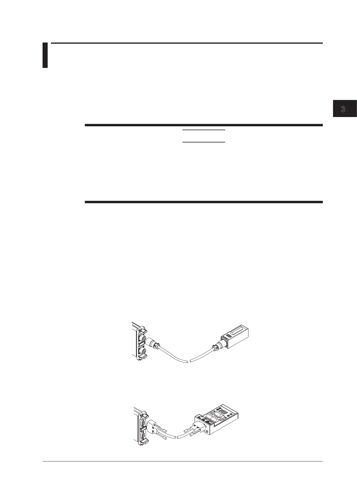
Connecting the Strain Module and the Bridge Head
When Using the Strain Module (701270) and the Bridge Head (701955/701956)
Using the cable that came with the bridge head (701955/701956), connect the Strain Module
(701270) and the bridge head.
Strain Module 701270
(STRAIN_NDIS)
Cable
Bridgehead
701955/701956
When Using the Strain Module (701271) and the Bridge Head (701957/701958)
Using the cable that came with the bridge head (701957/701958), connect the Strain Module
(701271) and the bridge head.
Cable
Bridgehead
701957/701958
Strain Module 701271
(STRAIN_DSUB)
3-25
IM DL850-03EN
Making Preparations for Measurements

 Loading...


