5.2 Trigger Output (TRIGGER OUT)
CAUTION
Do not short the TRIG OUT terminal or apply external voltage to it. Doing so may damage the
instrument.
External Trigger Output Terminal
When a trigger occurs, the DL850/DL850V produces a CMOS level signal. You can set the output
mode to normal or pulse. The signal level is normally high. It becomes low when a trigger occurs.
Item Specifications
Connector type BNC
Output level CMOS level (0 to 5 V)
Output formats Normal mode and pulse mode
Logic Normal mode Low when a trigger occurs and high after acquisition is
completed
Pulse mode Low when a trigger occurs and high after a specified period
of time has passed.
Output delay Normal mode Within 100 ns + 1 sample period
Pulse mode Within 100 ns + 1 sample period
Output hold time Normal mode 100 ns or more
Pulse mode 1 ms, 50 ms, 100 ms, or 500 ms
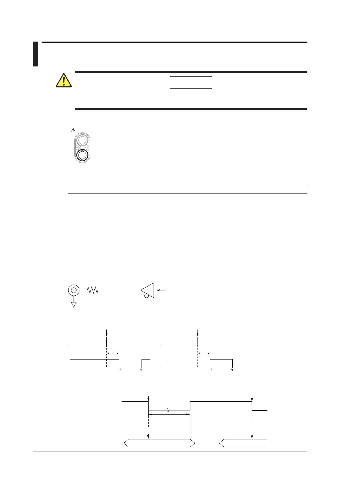
Circuit Diagram and Timing Chart for Trigger Output
EXT TRIG OUT
100 Ω
Equivalent to HC245
Trigger occurrence
(the time at the trigger position)
Trigger output
Internal trigger
Output hold time
Output delay
• Normal mode
Trigger occurrence
(the time at the trigger position)
Trigger output
Internal trigger
Output hold time
Output delay
• Pulse mode
Low Level and High Level Hold Times (In normal mode)
H
L
Trigger output
Post-trigger time
Trigger occurrence
Trigger occurrence
Pre
PostPost Pre
Waveform acquisition
Trigger Trigger

 Loading...


