3.14 Connecting Wires to the 16-CH Temperature/
Voltage Input Module
If you are using a 720221 (16CH TEMP/VOLT) to measure temperature and voltage, connect thermocouples or
wires to the 16-channel scanner box.
WARNING
• When connecting a device under measurement to the instrument, be sure to turn off the
device. It is extremely dangerous to connect or disconnect thermocouples or wires while
the device under measurement is on.
Precautions to Be Taken When Using the Modules
• T
o avoid electric shock, be sure to ground the instrument.
• To prevent the possibility of electric shock, be sure to fasten the module screws. Otherwise,
the electrical protection function and the mechanical protection function will not be activated.
Precautions to Be Taken When Using the 16-CH Scanner Box
• Do not connect or disconnect the 16-CH scanner box or the cables that are connected to it
while the power is on.
• Do not apply input voltage exceeding the maximum input voltage, withstand voltage, or
allowable surge voltage.
• Do not leave the instrument connected to devices in an enviro
nment that may be subject to
voltage surges.
• T
o prevent electric shock, connect wires to the terminal block that match the voltage range
that you are measuring.
• A
pplying a voltage exceeding the value indicated below may damage the input section. If the
frequency is above 1 kHz, damage may occur even when the voltage is below this value.
Maximum input voltage (across the input terminals, + and −,
1
at a frequency of 1 kHz or less)
42 V (DC + ACpeak)
Maximum allowable common
mode voltage (across the input terminals, + or −, and earth,
2
at a frequency of 1 kHz or less)
42 V (DC + ACpeak) (CAT II, 30 Vrms)
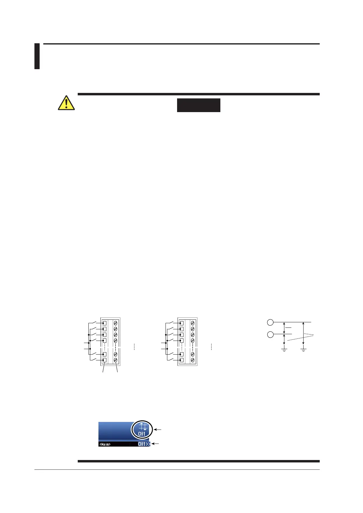
• The −
input terminals of the sub channels are electrically insulated inside the scanner
box. If you connect a wire that has a potential difference greater than 42 V (DC + ACpeak)
between sub channels, the insulation may be damaged, which will lead to the 16-CH
scanner box being damaged.
+
−
Input terminal
Ground
*2
*1
+
−
+
−
+
−
Wire insertion hole
Screwdriver insertion hole
Terminal block
Sub channel
CH 1
CH 2
CH 8
+
−
+
−
+
−
Terminal block
Sub channel
CH 9
CH 10
CH 16
Over-Range Indication
If over-range is indicated, the DL850/DL850V may be receiving a voltage higher than the
observed waveform or measured waveform values. To prevent electric shock, change the
vertical scale with the SCALE knob so that the entire amplitude of the waveform is displayed
within the waveform display area, and check the input voltage level.
Over-range indication
Indicates the number of the channel that over-range is occurring on.
Channel indication when over-range is occurring on multiple channels
Indicates the smallest number among the channels that over-range is
occurring on.
3-36
IM DL850-03EN

 Loading...


