3.5 Connecting Probes
Connecting Probes
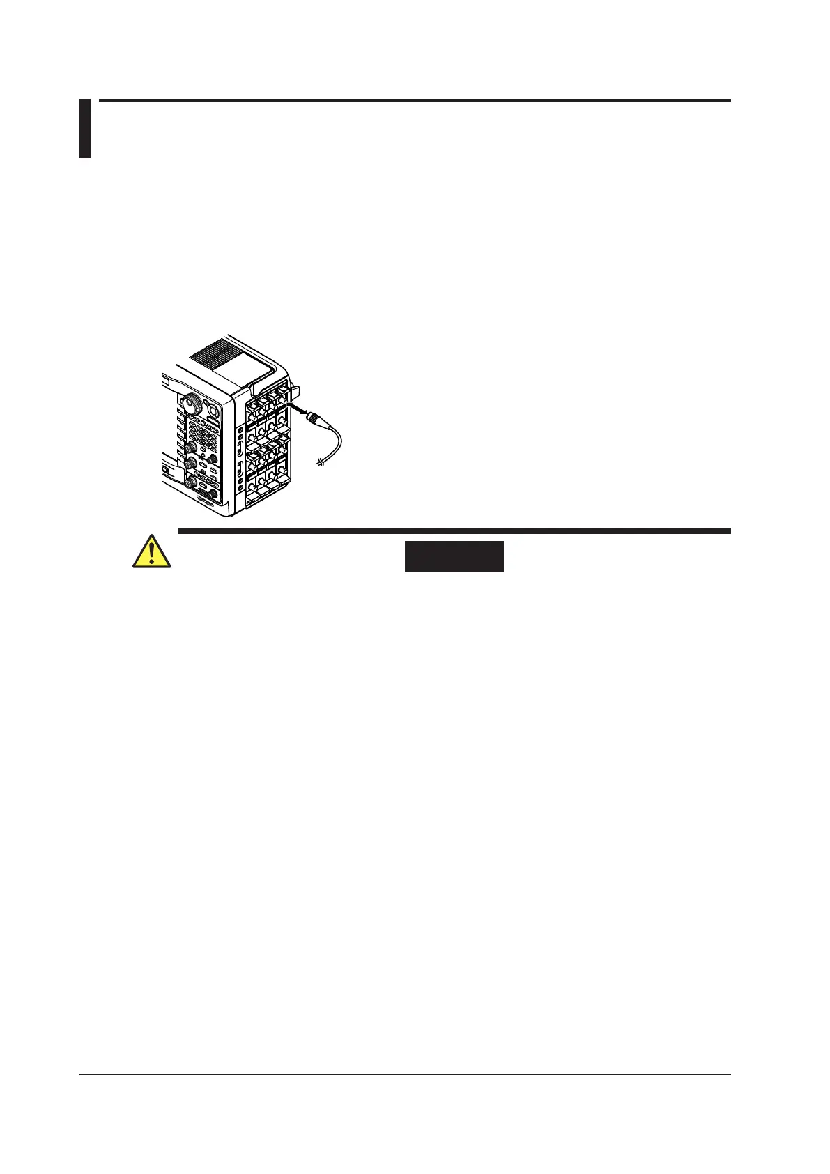
Connect the probes (or other input cables such as BNC cables) to any of the input terminals of the
following modules. The input impedance is 1 MΩ ± 1 % and approximately 35 pF.
• High-Speed 100 MS/s, 12-Bit Isolation Module:
720210 (HS100M12)
• High-Speed 10 MS/s, 12-Bit Isolation Module: 701250(HS10M12)
• High-Speed High-Resolution 1 MS/s, 16-Bit Isolation Module: 701251 (HS1M16)
• High-Speed 10 MS/s, 12-Bit Non-Isolation Module: 701255 (NONISO_10M12)
• Acceleration/Voltage Module (with AAF): 701275 (ACCL/VOLT)
• Frequency Module: 701280 (FREQ)
WARNING
• When connecting a device under measurement to the instrument, be sure to turn off the
device. It is extremely dangerous to connect or remove measurement leads while the
device under measurement is on.
Precautions to Be Taken When Using the Modules
•
Do not apply input voltage exceeding the maximum input volta
ge, withstand voltage, or
allowable surge voltage.
• T
o avoid electric shock, be sure to ground the instrument.
• To prevent the possibility of electric shock, be sure to fasten the module screws. Otherwise,
the electrical protection function and the mechanical protection function will not be
activated.
• Do not leave the instrument connected to devices in an enviro
nment that may be subject to
voltage surges.
• Use only specified cables. It is extremely dangerous to use ca
bles that do not meet the
safety standards. (Especially when you are handling high voltages of 42 V or more.)
• When measuring high voltages using the 720210 (HS100M12
), 701250 (HS10M12), or
701251 (HS1M16), use an isolated probe (the 700929 or 701947), 1:1 safety cable (a
combination of the 701901 and 701954), or differential probe (700924).
•
The BNC portion of the 10 MHz passive probe (701940) is me
tal, so if you use it with
isolated input (the 720210 (HS100M12), 701250 (HS10M12), 701251 (HS1M16), 701275
(ACCL/VOLT), or 701280(FREQ)), for safety, be sure to only use it with voltages at or
below 42 V. (Do not connect voltage above 42 V to both the High and Low sides.)For non-
isolated inputs (701255 (NONISO_10M12), etc.), fasten the module screws.
•
W
hen you apply high voltages to the 701280 (FREQ), use an isolated probe (the 700929 or
701947).
In Using the High Voltage Differential Probes
Be sure to connect the GND lead of a differential probe (the 700924 or 700925) to the
functional ground terminal on the right side panel of the instrument. Otherwise, high voltage
may appear at the BNC connector making it dangerous.
3-14
IM DL850-03EN

 Loading...


