3.8 Connecting Thermocouples
Connecting Thermocouples
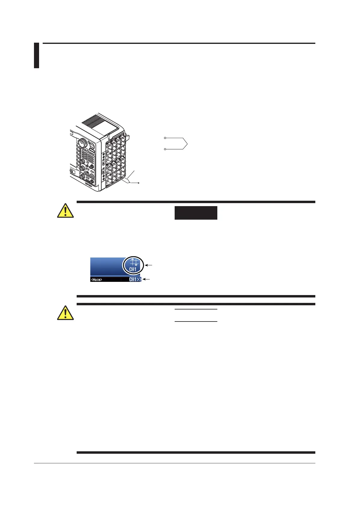
If you are connecting the compensation lead of the thermocouple to the input terminal (binding post
terminal) of the 701261 (UNIVERSAL), 701262 (UNIVERSAL (AAF)), or 701265 (TEMP/HPV), loosen
the terminal knob, pass the lead through the terminal, and tighten the knob.
To the thermocouple
L
H
Extension wires
(or bare thermocouple wires)
Positive lead
Negative lead
WARNING
Over-Range Indication
If over-range is indicated, the DL850/DL850V may be receiving a voltage higher than the
observed waveform or measured waveform values. To prevent electric shock, change the
vertical scale with the SCALE knob so that the entire amplitude of the waveform is displayed
within the waveform display area, and check the input voltage level.
Over-range indication
Indicates the number of the channel that over-range is occurring on.
Channel indication when over-range is occurring on multiple channels
Indicates the smallest number among the channels that over-range is
occurring on.
CAUTION
• The 701261 (UNIVERSAL), 701262 (UNIVERSAL (AAF)), or 701265 (TEMP/HPV) is
isolated from the DL850/DL850V. However, applying a voltage exceeding the value below
may damage the input section. If the frequency is above 1 kHz, damage may occur even
when the voltage is below this value.
Maximum input voltage (across the input terminals, H and L, at a frequency of 1 kHz or less)
42 V (DC + ACpeak)
Maximum allowable common mode voltage (across the input terminal L and earth at a
frequency of 1 kHz or less)
42 V (DC + ACpeak) (CAT II, 30 Vrms)
•
Correct measurements cannot be obtained when the positive
and negative thermocouple
leads are connected in reverse.
• Immediately after connecting the thermocouple, the heat balance may be disturbed at
the input terminal section and may cause measurement errors.
Therefore, wait about ten
minutes before making a measurement.
•
In an environment where the air from the air conditioning is directly applied to the input
terminals or where there are ef
fects from a heat source, the heat balance may be disturbed
at the input terminal section and cause measurement errors.
When making measurements in this type of environment, take preventive measures such
as changing the position.
3-24
IM DL850-03EN

 Loading...


