3.15 Connecting a Cable to the CAN Bus Monitor
Module
To monitor CAN bus signals, connect a cable to the CAN bus monitor module’s D-sub connector.
Connector Pinout
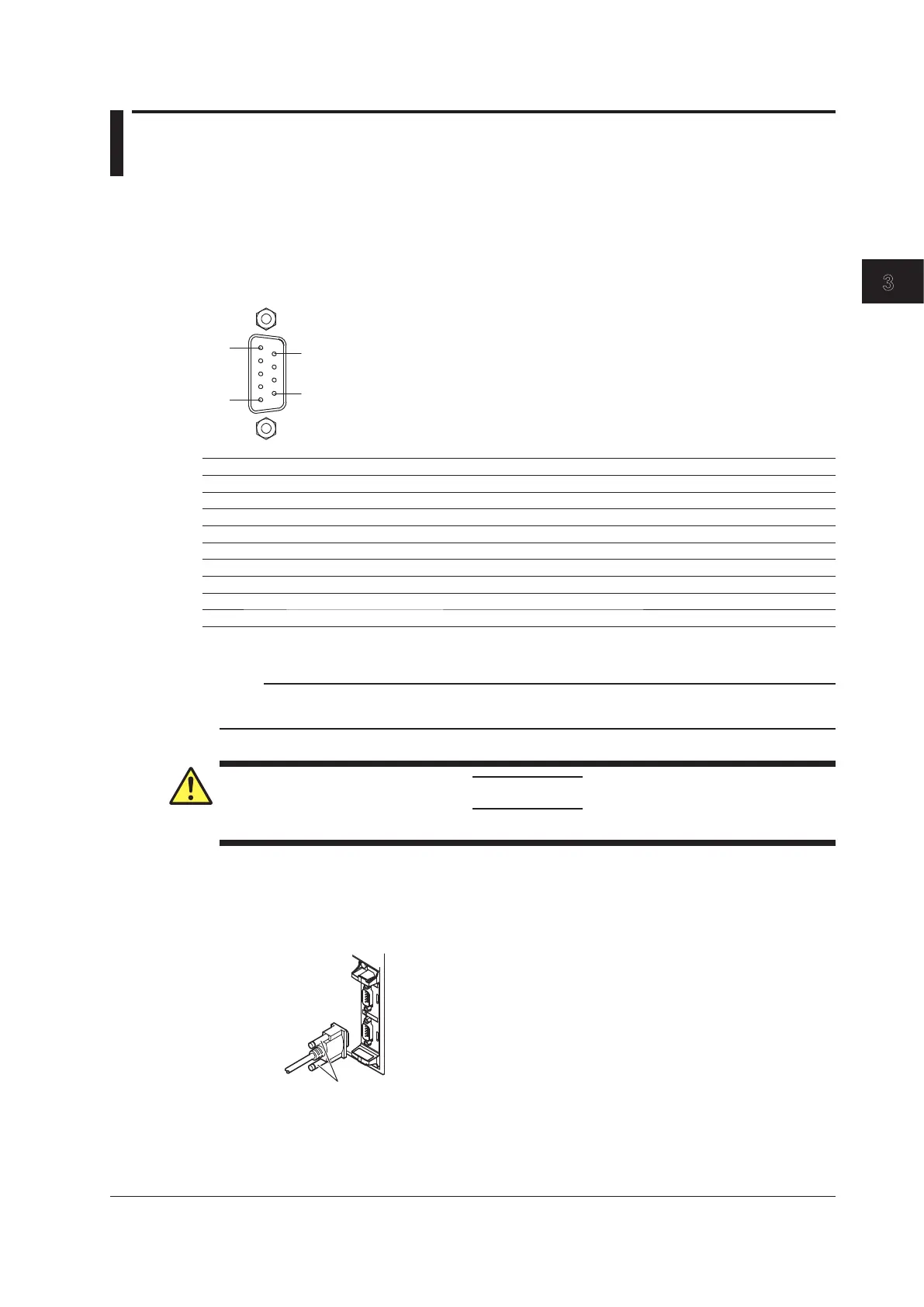
The pinout of the D-sub connector (9 pin, male) is shown below.
Pin No. Signal Function
1 (NC) Not used (can not be connected to)
2 CAN_L CAN low signal
3 GND Ground
4 (NC) Not used (can not be connected to)
5 (NC) Not used (can not be connected to)
6 GND Ground
7 CAN_H CAN high signal
8 (NC) Not used (can not be connected to)
9 (NC) Not used (can not be connected to)
* One-inch screws (number 4-40 UNC) are used.
Note
The connector shell is connected to GND. Additionally, GND and the connector shell are isolated from the
electric potential of the DL850/DL850V case (earth).
CAUTION
Applying a voltage greater than the maximum input voltage may damage the input section.
Connecting the Cable (Signal wires)
When you connect a cable to the D-sub connector, be sure to tighten the screws to ensure that the
cable is connected securely.
CAN bus monitor module
720240 (CAN MONITOR)
Cable
Screws
3-39
IM DL850-03EN
Making Preparations for Measurements

 Loading...


