7.
Insert the protection cover into the guide hole.
8.
Tighten the protection cover screw using a screwdriver.
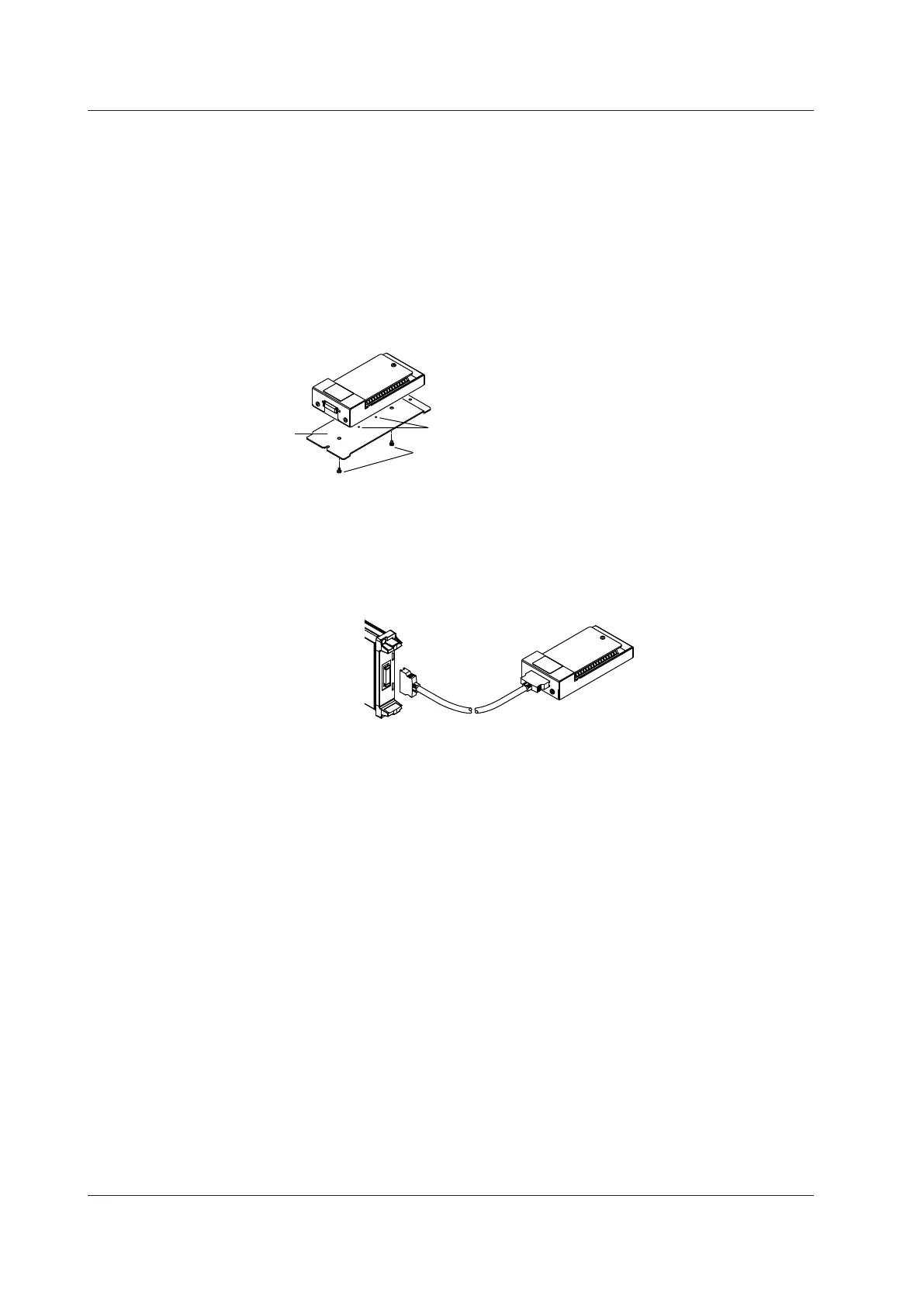
Fixing the Device in Place
If necessary, you can use the accessory attaching plate, B8074LN, to fix the scanner box to the panel.
1.
Align the small holes on the bottom side of the scanner box to the small projections of the
attaching plate.
2.
Screw the scanner box and the attaching plate together using the accessory binding screws (M4
× 5 mm).
Screw tightening torque: 1.2 N•m
Binding screws
(M4 x 5mm)
Attaching
plate
B8074LN
Projections
Connecting the 16-CH Temperature/Voltage Input Module and the
Scanner Box
Using the cable that came with the scanner box (701953), connect the 720221 (16CH TEMP/VOLT)
and the scanner box.
Cable
16-CH Scanner Box
701953
16-CH Temperature/Voltage
Input Module
720221
(16CH TEMP/VOLT)
3.14 Connecting Wires to the 16-CH Temperature/Voltage Input Module
3-38
IM DL850-03EN

 Loading...


