3.6 Correcting the Probe Phase
For the following modules, always correct the probe phase before you use a probe for measurement.
• High-Speed 100 MS/s, 12-Bit Isolation Module: 720210 (HS100M12)
•
High-Speed 10 MS/s, 12-Bit Isolation Module:
701250 (HS10M12)
• High-Speed High-Resolution 1 MS/s, 16-Bit Isolation Module: 701251 (HS1M16)
• High-Speed 10 MS/s, 12-Bit Non-Isolation Module:
701255 (NONISO_10M12)
• Acceleration/Voltage Module (with AAF):
701275 (ACCL/VOLT)
• Frequency Module:
701280 (FREQ)
CAUTION
Do not apply external voltage to the probe compensation signal output terminal. This may
cause damage to the internal circuitry.
1.
Turn on the power switch.
2.
Connect the probe to a signal input terminal (the terminal that you will actually apply the signal
to measure to).
3.
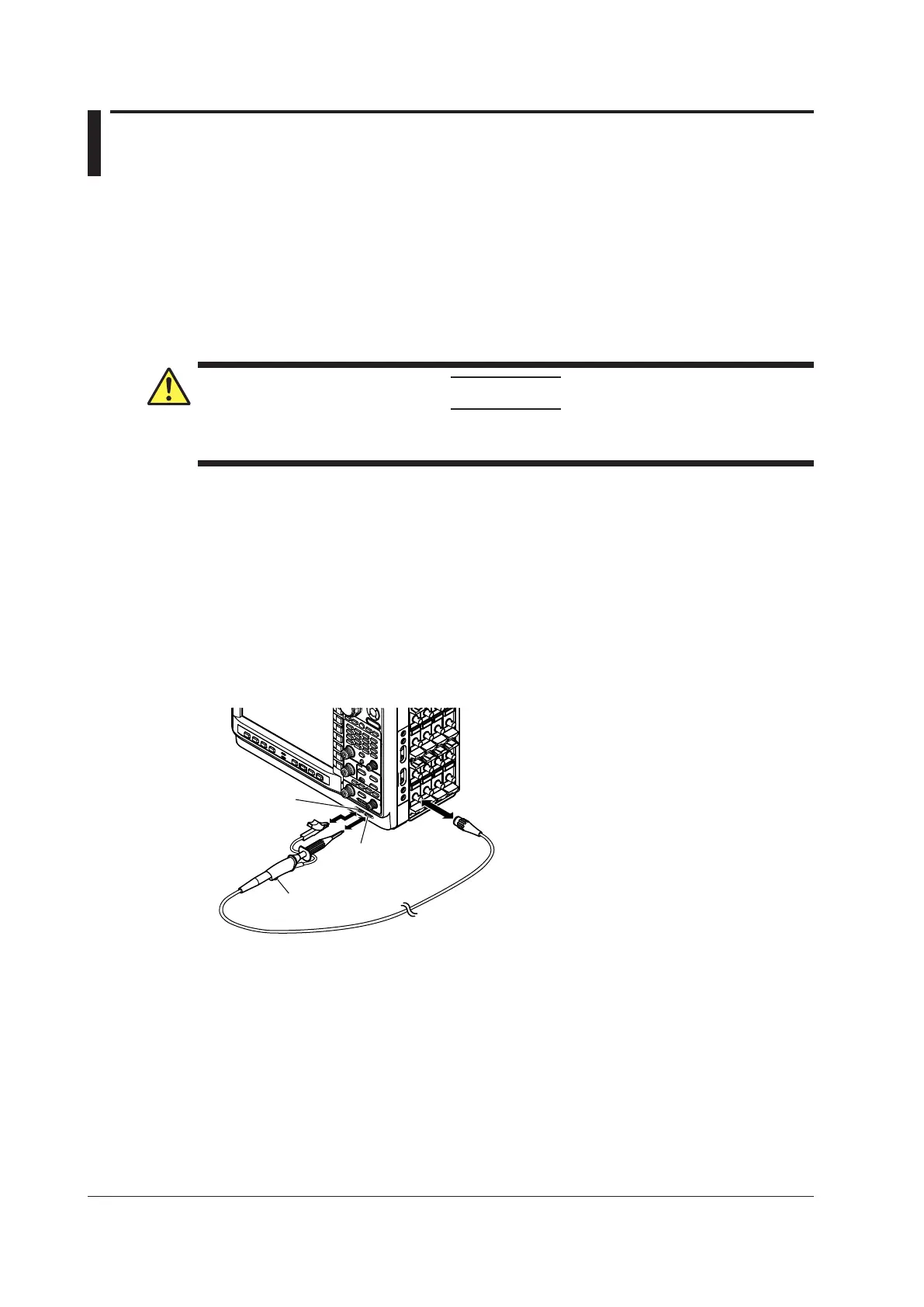
Connect the tip of the probe to the probe compensation signal output terminal on the front panel
of the instrument, and connect the ground wire to the functional ground terminal.
4.
Follow the instructions in section 4.5,
“
Performing Auto Setup,” to perform auto setup on the
probe.
5.
Insert a screwdriver into the phase adjustment hole, and turn the variable capacitor so that the
displayed waveform is an appropriate square wave.
Probe compensation
signal output terminal
Functional
ground terminal
Phase adjustment
hole
Necessity of Phase Correction of the Probe
If the probe’s input capacitance is not within the appropriate range, the gain will not be steady in
relation to the frequency, and waveforms will not be displayed correctly. Also, because the input
capacitance is not the same for each probe, the probe’s have variable capacitors (trimmers) that need
to be adjusted. This adjustment is referred to as phase correction.
Always correct the phase of a probe that you are using for the first time.
Also, because the appropriate input capacitance range is different for each channel, you need to
perform phase correction when you change the channel that a probe is connected to.
3-20
IM DL850-03EN

 Loading...


