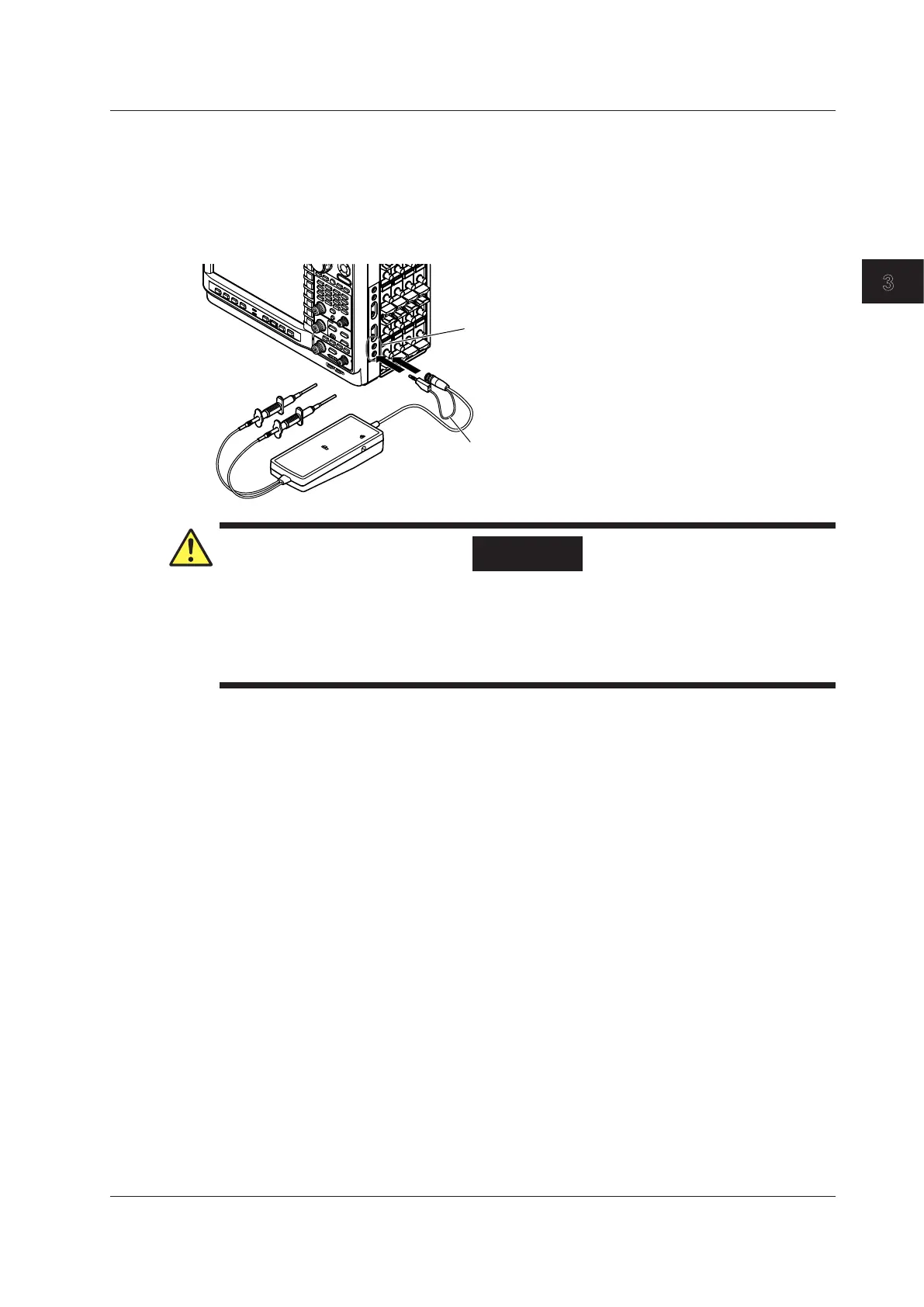
Connecting Differential Probes (700924)
When using differential probes (700924) made by YOKOGAWA, connect the BNC output connector
to the input terminal of the oscilloscope. Also, be sure to connect the GND lead to the functional
ground terminal of the DL850/DL850V. If necessary, use the auxiliary grounding lead extension. A
measurement of 1400 Vpeak is possible by connecting the GND lead to the DL850/DL850V.
For details on the connection procedure, see the manual that came with the differential probe.
Functional ground terminal
GND lead
WARNING
In Using the High Voltage Differential Probes
Be sure to connect the GND lead of a differential probe (the 700924 or 700925) to the
functional ground terminal on the right side panel of the DL850/DL850V. Otherwise, high
voltage may appear at the BNC connector making it dangerous. Also, be sure to connect the
GND lead to the DL850/DL850V before you connect to the device under measurement.
3.5 Connecting Probes
3-19
IM DL850-03EN
Making Preparations for Measurements

 Loading...


