3.12 Connecting Sensors to the Frequency Module
Sensors and Signal Output Sources That Can Be Connected
The table below shows the sensor and signal output source that can be connected. Appropriate input
presets are provided for each sensor and signal output source. For information about presets, see
Input Setup in section 1.7,
“
Configuring Frequency, Revolution, Period, Duty Cycle, Power Supply
Frequency, Pulse Width, Pulse Integration, and Velocity Measurements,” in the user’s manual.
Sensor and Signal Output Source Preset Name
5-V logic signal, 5-V output sensor, and sensor with TTL output Logic 5V
3-V logic signal and 3-V output sensor Logic 3V
12-V driven relay/sequence circuit and 12-V driven sensor Logic 12V
24-V driven relay/sequence circuit and 24-V driven sensor Logic 24V
Sensor/Encoder that outputs positive and negative voltages and sensor that outputs sine waves ZeroCross
100-VAC power supply (connected via the isolated probe (700929)) AC100V
200-VAC power supply (connected via the isolated probe (700929)) AC200V
Power-generating electromagnetic pickup EM Pickup
Open collector (0 to 5 V) output sensor, contact output Pull-up 5V
*
* For the internal equivalent circuit when the preset setting is Pull-up 5V, see the “Frequency Measurement”
section in chapter 2, “Vertical Axis” in the feature’s guide (IM DL850-01EN).
Precautions to Be Taken When Connecting to Sensors or Signal
Output Sources
WARNING
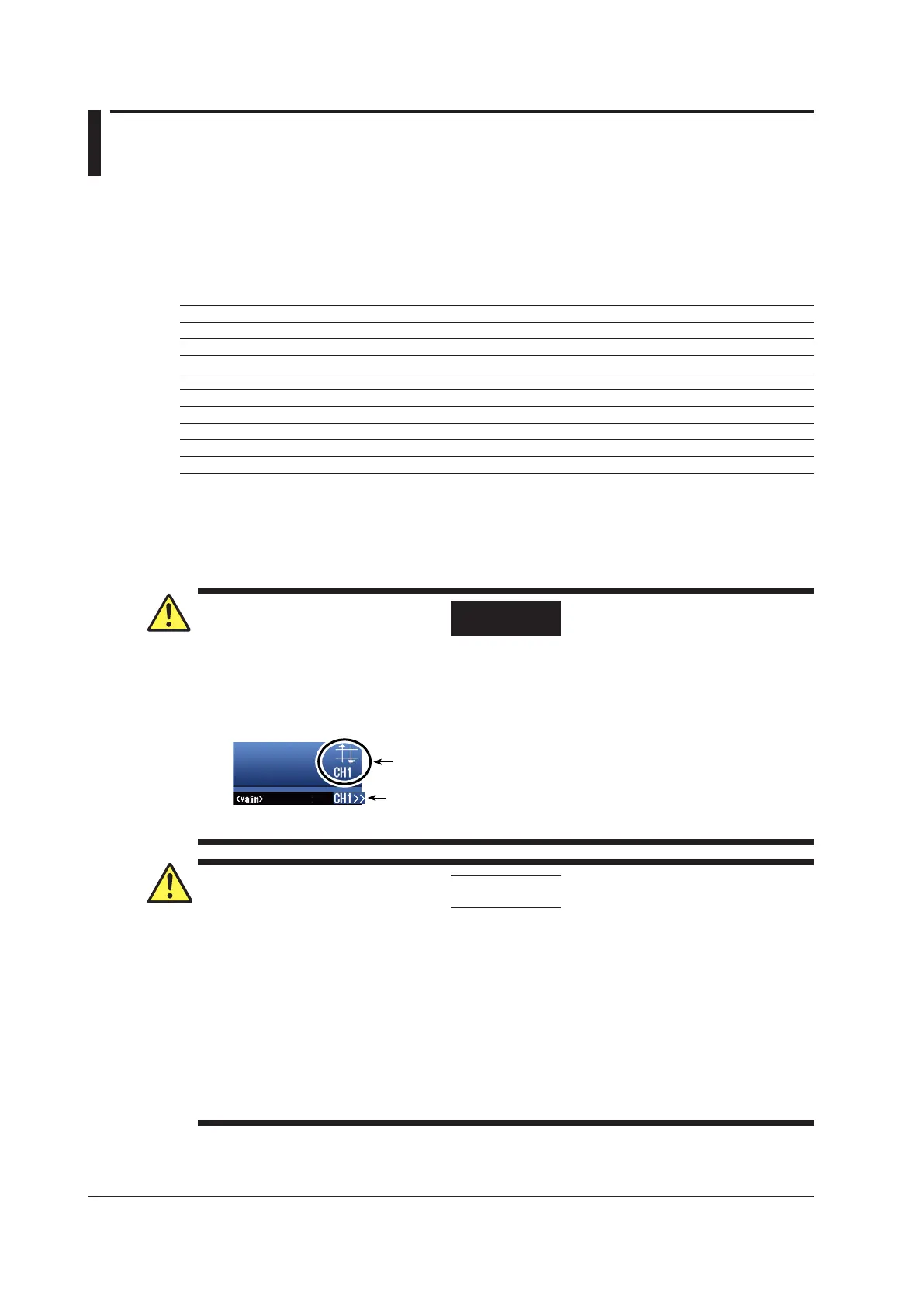
Over-Range Indication
If over-range is indicated, the DL850/DL850V may be receiving a voltage higher than the
observed waveform or measured waveform values. To prevent electric shock, change the
vertical scale with the SCALE knob so that the entire amplitude of the waveform is displayed
within the waveform display area, and check the input voltage level.
Over-range indication
Indicates the number of the channel that over-range is occurring on.
Channel indication when over-range is occurring on multiple channels
Indicates the smallest number among the channels that over-range is
occurring on.
CAUTION
• The maximum input voltage for direct input is indicated below. Applying a voltage exceeding
this value can damage the input section. When applying a high voltage of 42 V or more, be
sure to use an isolated probe (the 700929 or 701947).
Maximum input voltage:
42 V (DC +
ACpeak) (CAT II)
• The minimum input voltage is 0.2 Vpp.
At voltage amplitude less than 0.2 Vpp, the
measured values may be unstable.
•
Attach/Remove the sensors after confirming that the rotating object to be measured is
stopped.
•
Set the preset to electromagnetic pickup (EM Pickup) only when using the electromagnetic
pickup.
3-32
IM DL850-03EN

 Loading...


