EasyManuals Logo

YOKOGAWA DL850 ScopeCorder User Manual

YOKOGAWA DL850 ScopeCorder
190 pages
To Next Page IconTo Next Page
To Previous Page IconTo Previous Page
Page #74 background imageLoading...
Page #74 background image
Connecting the Electromagnetic Pickup
The DL850/DL850V allows power-generating electromagnetic pickup to be connected directly. The
DL850/DL850V does not support electromagnetic pickups that require external power supply or
those that require a terminator at the output.
T
o connect electromagnetic pickups, use BNC cables. Use cables that are appropriate for the
electromagnetic pickups being used.
When the input is set to electromagnetic pickup, determination is not made on whether the input
voltage level exceeds the specified input voltage range.
Therefore, the LEDs (see page 3-8) do not
illuminate eve when the input voltage level is over range.
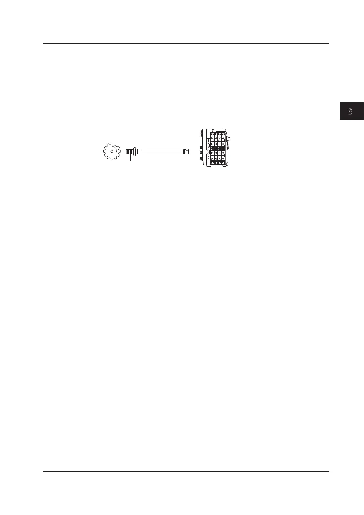
701280 (FREQ)
Power-generating
electromagnetic pickup
Rotating object under
measurement
BNC connector
DL850/DL850V
3.12 Connecting Sensors to the Frequency Module
3-33
IM DL850-03EN
Making Preparations for Measurements
1
2
3
4
5
6
App
Index

Table of Contents

Questions and Answers:

Question and Answer IconNeed help?

Do you have a question about the YOKOGAWA DL850 ScopeCorder and is the answer not in the manual?

YOKOGAWA DL850 ScopeCorder Specifications

General IconGeneral
Maximum Sampling Rate100 MS/s
Power Supply100 to 240 VAC, 50/60 Hz
Resolution16-bit
Operating Temperature5 to 40°C
Bandwidth20 MHz
Input TypesVoltage, Temperature, Strain, Acceleration, Frequency, Logic, Current
InterfacesEthernet, USB, GP-IB
Trigger ModesEdge, Window, Pattern
Number of ChannelsUp to 128 (with multiple input modules)
Memory CapacityUp to 2 G points (with /M4 option)

Related product manuals