Types of Measurement Leads That Can Be Used on the Isolated Logic Probe (700987)
Use the following measurement lead.
• For measuring voltages of 42 V or more: Measurement lead for isolation logic (758917)
An alligator adapter (758922), alligator adapter (758929), or alligator clip (dolphin type, 701954)
is needed to make measurements.
Note
Do not modify the connecting leads. Doing so may degrade their specifications.
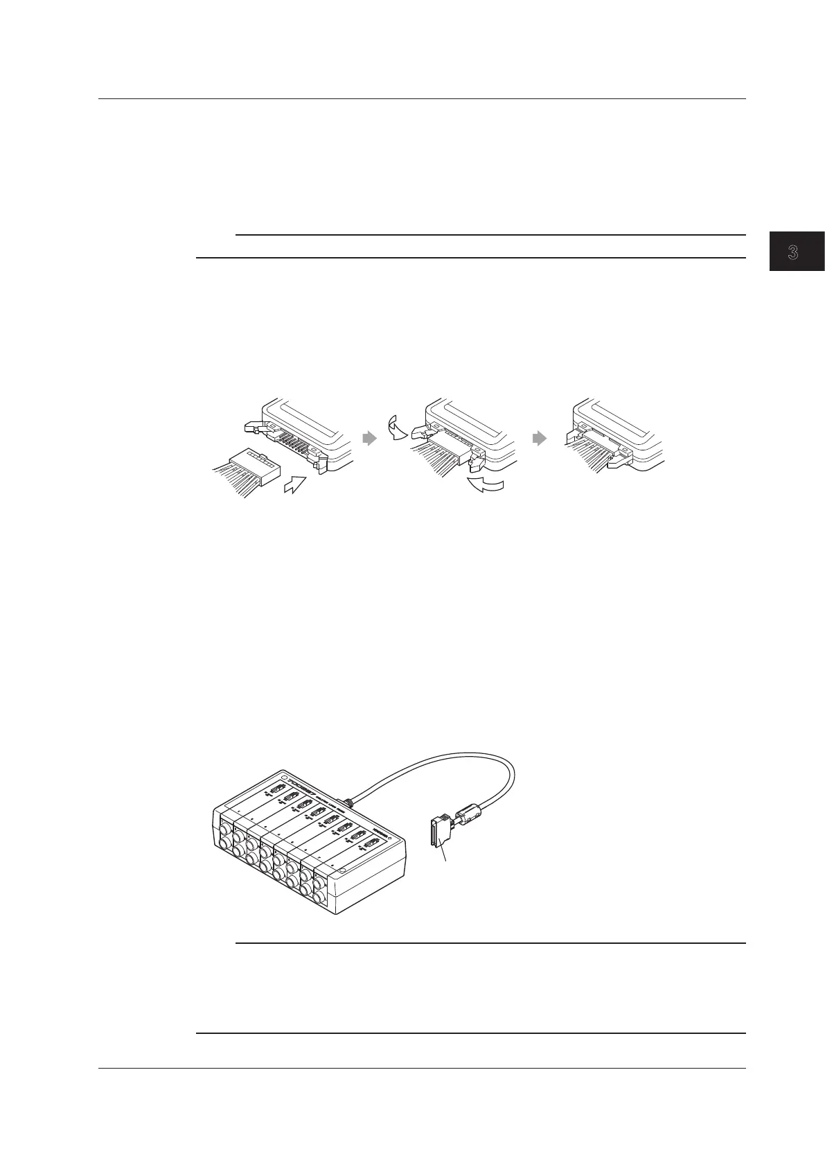
Connecting Logic Probes
Connecting Logic Probes 702911, 702912, and 700986
1.
Attach the connecting lead (IC clip or alligator clip) that came with the logic probe, and push
the logic probe levers inwards to lock the connector into place. To remove the connecting leads
from the logic probe, push both of the levers outwards. Proceed to step 3.
Connecting the Isolated Logic Probe (700987)
1.
Connect the measurement leads to the logic probe’s input terminal.
2.
Set the input switch. When you set it to AC, the threshold levels are 50 VAC ± 50% (Hi: 80 to
250 VAC, Lo: 0 to 20 VAC); when you set it to DC, the threshold levels are 6 V ± 50% (Hi: 10 to
250 VDC, Lo: 0 to 3 VDC).
Connecting the Logic Probe to a Logic Input Module
3.
Turn the instrument’s power switch off.
4.
Connect to the logic signal input connector of the logic input module (720230) the end of the
logic probe’s 26-pin connector that has a clamp filter (ferrite core; part number: A1190MN).
5.
Turn on the DL850/DL850V.
To the logic signal input connector
of the logic input module
Note
• When a logic probe is not connected to the DL850/DL850V, each bit is indicated as being at the high
level.
• For the logic probe specifications, see section 6.14, “Logic Probe Specifications.”
• The logic input display is turned off by default. For information about turning the display on and off, see
chapter 1, “Vertical and Horizontal Control,” in the user’s manual.
3.10 Connecting a Logic Probe to the Logic Input Module
3-29
IM DL850-03EN
Making Preparations for Measurements

 Loading...


