5-5
IM DL850-03EN
External Signal I/O
5.5 GO/NO-GO Determination I/O and External
Start/Stop Input (EXT I/O)
Connecting to Other Instruments
CAUTION
• Do not apply external voltage to the NO-GO OUT and GO OUT output pins. Doing so may
damage the instrument.
• When connecting the GO/NO-GO determination signal output
to another device, do not
connect the wrong signal pin. Doing so may damage the DL850/DL850V or the connected
instrument.
• Do not connect a USB cable to the GO/NO-GO output terminal. Doing so may damage the
instrument.
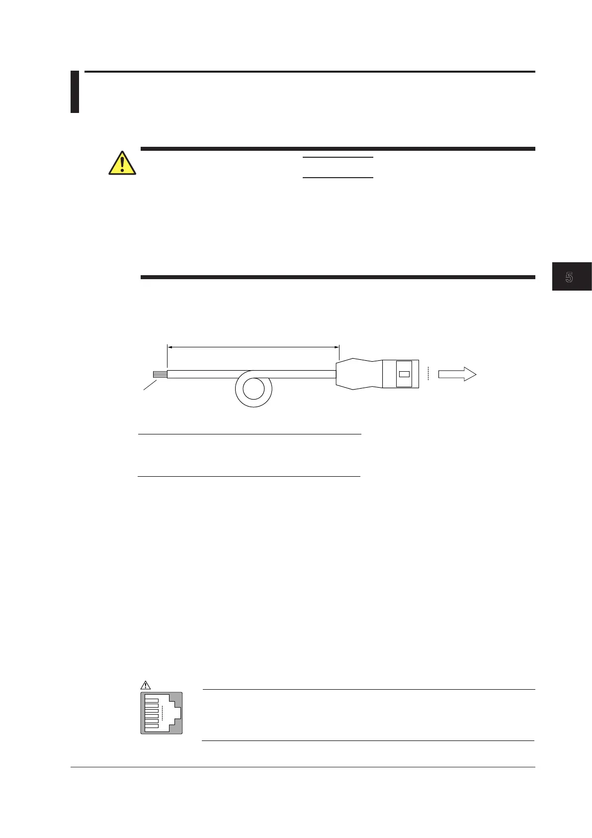
About the External I/O Cable (720911; sold separately)
• Do not use the cable for anything other than the DL850/DL850V external I/O.
• Refer to the following figure to connect the cable to an external device.
1
6
Approx. 1.5 m
RJ-11 connector
To the DL850/DL850V
Process the wires at the
end of the stripped cable
as necessary.
Pin no. Signal Logic
1 EXT EVENT IN Negative logic
Wire color
Red
2
3
4
5
START IN
GO OUT
NOGO OUT
Negative logic
Negative logic
Negative logic
GND
Yellow
White
Green
Blue
GO/NO-GO Determination I/O
You can apply an external signal to the DL850/DL850V’s GO/NO-GO I/O terminal and perform GO/
NO-GO determination, and you can output the results of GO/NO-GO determination from the GO/NO-
GO I/O terminal.
GO/NO-GO I/O Connector
Type
The connector uses an RJ-11 modular jack. Use the external I/O cable accessory (720911; sold
separately). If you are using a commercially sold cable (four-conductor modular telephone cable),
wire the pins according to the above figure.
I/O Level
Within 0 to 5 V, threshold level: TTL
Pinout
6
1
1
Pin no. Signal
2
3
4
5
6
EXT EVENT IN
START IN
GO OUT
NOGO OUT
IN
Connector on
the DL850
OUT
OUT
Starts on low edge
Active low (GO)
Active low (NO-GO)
GND
NC (no connection)
EXT I/O
Manual event. Event input occurs on low edge.
IN

 Loading...