What to Prepare
Wiring
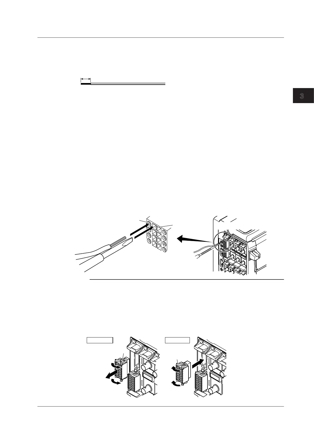
Remove approximately 7 mm of the insulation from the ends of the wires.
Electrical wire: 0.20 mm
2
to 1.00 mm
2
recommended (solid wire or thin stranded wire). AWG
size: 24-18.
Flat-blade Screwdriver
Tip size: 0.4 mm (thickness) × 2.5 mm (width)
Shape: DIN5264-A (Use a straight driver.)
Connecting Wires to the Terminal Block
First, turn off the DL850/DL850V. Make sure that the other end of the wire that you are connecting to
the terminal block is not connected to the device under measurement, or make sure that the device
under measurement that you are going to connect to is turned off.
1.
Insert the flat-blade screwdriver into the screwdriver insertion hole right next to the wire
insertion hole.
If you do not insert the flat-blade screwdriver into the hole firmly, the wire insertion hole will not open.
2.
Insert the wire that you prepared into the wire insertion hole.
Insert the wire until it reaches the back of the wire insertion hole.
3.
Pull the flat-blade screwdriver out of the screwdriver insertion hole.
When you pull out the flat-blade screwdriver, hold the wire in place so that it does not come out with the
screwdriver.
4.
Pull lightly on the wire to make sure that it doesn’t come out.
After you have finished connecting the wires, turn on the DL850/DL850V and the device under
measurement.
Wire
Flat-blade screwdriver
Terminal block
Module: 720220 (16CH VOLT)
Wire insertion hole
Screwdriver
insertion hole
Note
Removing and Attaching the Terminal Block
It is normally not necessary to remove the terminal block, but it is possible to do so.
Removal
Push terminal block release levers 1 and 2 to their release positions, and pull out the terminal block.
Attachment
Push terminal block release levers 1 and 2 to their lock positions, and insert the terminal block. Push the
terminal block firmly all the way to the back. However, the terminal block will not go all the way to the back
if it is upside down. Do not try to force the terminal block all the way to the back.
Release lever 1
Release lever 2
Hold
Release
Removing Attaching
3.13 Connecting Wires to the 16-CH Voltage Input Module
3-35
IM DL850-03EN
Making Preparations for Measurements

 Loading...


