6-30
IM DL850-03EN
Item Specifications
Input bias current 20 nA or less
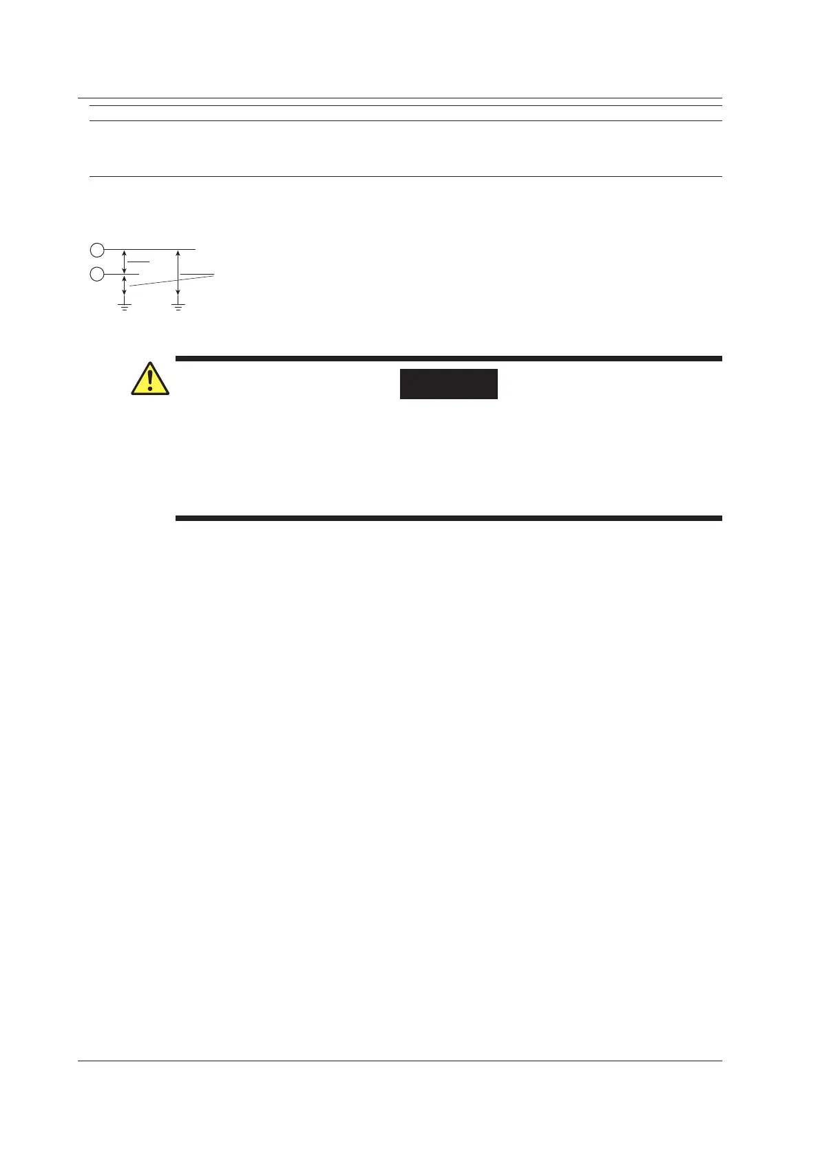
The zero point appears to be offset when the input is open due to the effects of bias current
on this module. However, this is not a malfunction.
Connect the input to the object to be measured.
1 V
alue measured under standard operating conditions.
2 Does not include the reference junction temperature compensation accuracy.
3 This module supports Au7Fe with 0.07% metal content with respect to gold.
6 The typical value is a representative or standard value. It is not strictly warranted.
WARNING
• Do not apply input voltage exceeding the maximum input voltage or allowable common
mode input voltage.
• T
o prevent the possibility of electric shock, be sure to furnish protective earth grounding of
the DL850/DL850V.
• T
o prevent the possibility of electric shock, be sure to fasten the module screws.
Otherwise, the electrical and mechanical protection functions will not be activated.
6.13 Module Specifications

 Loading...


