Precautions to Be Taken When Connecting Probes
• When connecting a probe to the instrument for the first time, perform phase correction of the probe
as described in section 3.6, “Compensating the Probe (Phase Correction).” Failure to do so will
cause unstable gain across different frequencies, thereby preventing correct measurement. Make
the phase correction on each channel to which the probe is to be connected.
•
Y
ou cannot perform phase correction of the probe on the frequency module (701280(FREQ)).
When connecting a probe to the 701280 (FREQ), first perform phase correction on the probe using
another module.
• If the object to be measured is connected to the instrument dir
ectly, without using a probe, a correct
measurement cannot be performed due to the input impedance. Please be aware of this.
• Please be aware that if you use a voltage probe that is not an
isolated probe (the 700929 or
701947) and whose attenuation is not 1:1, 10:1, 100:1, or 1000:1, the correct measured values
cannot be displayed.
• Follow the instructions given in section 1.1, “Configuring V
oltage Measurements,” in the user’s
manual to set the probe attenuation (type) to match the actual value using the setup menu. If they
do not match, measured values cannot be read correctly.
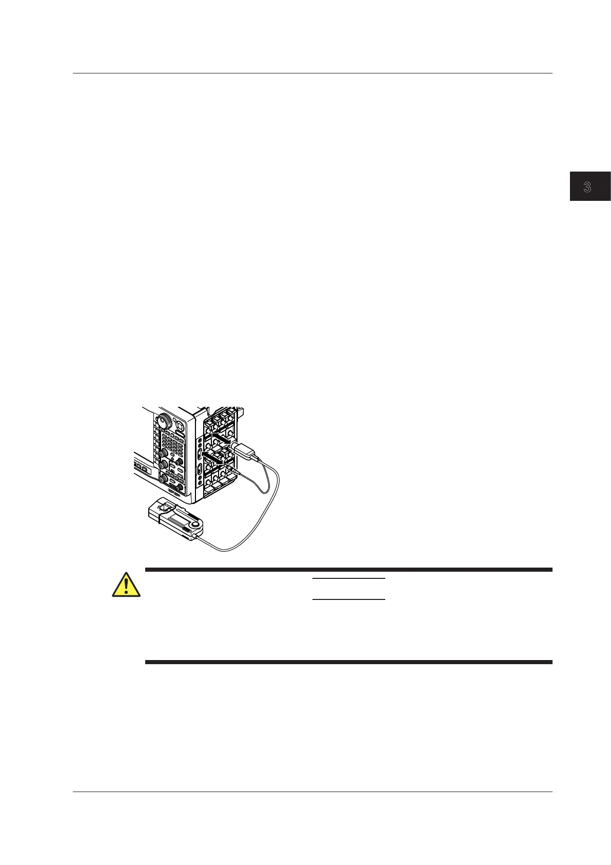
Connecting Current Probes
When using current probes made by YOKOGAWA,
*
use the probe power supply (optional) on the right
side panel of the DL850/DL850V.
* YOKOGAWA current probes: the 700937, 701930, 701931, and 701933
For details on the connection procedure, see the manual that came with the current probe.
CAUTION
Do not use the probe power supply terminals (optional) on the right side panel of the DL850/
DL850V for purposes other than supplying power to the current probes. Also, be sure to use
only the number of probes allowed. Otherwise, the DL850/DL850V or the devices connected
to them may get damaged.
3.5 Connecting Probes
3-17
IM DL850-03EN
Making Preparations for Measurements

 Loading...


