• For the 701275 (ACCL/VOLT)
Maximum input voltage (at a frequency of 1 kHz or less)
• Combined with the 701940 (10:1) passive probe
11
or direct input (cable that does not
comply with the safety standards)
9
42 V (DC + ACpeak)
Maximum allowable common mode voltage (at a frequency of 1 kHz or less)
• Combined with the
701940 (10:1) passive probe
12
or direct input (cable that does not
comply with the safety standards)
10
42 V (DC + ACpeak) (CAT II, 30 Vrms)
• For the 701280 (FREQ)
Maximum input voltage (at a frequency of 1 kHz or less)
• When used with the 700929 (10:1) isolated probe or the 701947 (100:1) isolated probe.
1
420 V (DC + ACpeak)
•
Safety cable (1:1) (combined with 701901 + 701954)
5
or direct input (cable that does
not comply with the safety standards)
9
42 V (DC + ACpeak)
Maximum allowable common mode voltage (at a frequency of 1 kHz or less)
•
When used with the 700929 (10:1) isolated probe or the 701947 (100:1) isolated probe.
2
300 Vrms (CAT II)
• Safety cable (1:1) (combined with 701901 + 701954)
8
or direct input (cable that does
not comply with the safety standards)
10
42 V (DC + ACpeak) (CAT II, 30 Vrms)
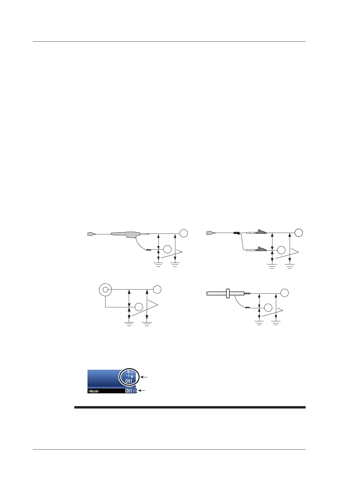
H
L
With the 700929 or 701947
1
2
700929/701947
H
L
701901
701954
5
With the 701901 and 701954
H
L
Direct input (cable that does not comply
with the safety standards)
9
10
BNC
8
3
4
6
7
With the 10:1 passive probe (701940)
H
L
11
12
Over-Range Indication
If over-range is indicated, the DL850/DL850V may be receiving a voltage higher than the
observed waveform or measured waveform values. To prevent electric shock, change the
vertical scale with the SCALE knob so that the entire amplitude of the waveform is displayed
within the waveform display area, and check the input voltage level.
Over-range indication
Indicates the number of the channel that over-range is occurring on.
Channel indication when over-range is occurring on multiple channels
Indicates the smallest number among the channels that over-range is
occurring on.
3.5 Connecting Probes
3-16
IM DL850-03EN

 Loading...


