EasyManuals Logo

YOKOGAWA DL850 ScopeCorder User Manual

YOKOGAWA DL850 ScopeCorder
190 pages
To Next Page IconTo Next Page
To Previous Page IconTo Previous Page
Page #68 background imageLoading...
Page #68 background image
Pinout of the D-Sub Connector
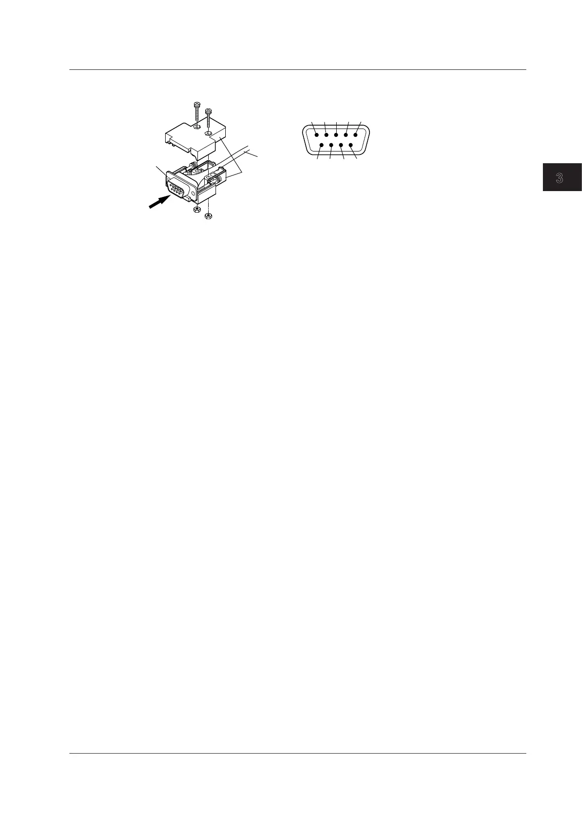
As viewed in the direction of arrow 1
5
4
3
21
9
8
7
6
1: Floating common
2: Sense– (negative bridge voltage sensing)
3: Shuntcal– (negative shunt signal)
4: Shuntcal+ (positive shunt signal)
5: Sense+ (positive bridge voltage sensing)
6: Bridge– (negative bridge voltage)
7: Input– (negative measurement signal)
8: Input+ (positive measurement signal)
9: Bridge+ (positive bridge voltage)
D-Sub 9-pin
connector
Connector shell
Cable
1
3.9 Connecting Bridgeheads
3-27
IM DL850-03EN
Making Preparations for Measurements
1
2
3
4
5
6
App
Index

Table of Contents

Questions and Answers:

Question and Answer IconNeed help?

Do you have a question about the YOKOGAWA DL850 ScopeCorder and is the answer not in the manual?

YOKOGAWA DL850 ScopeCorder Specifications

General IconGeneral
Maximum Sampling Rate100 MS/s
Power Supply100 to 240 VAC, 50/60 Hz
Resolution16-bit
Operating Temperature5 to 40°C
Bandwidth20 MHz
Input TypesVoltage, Temperature, Strain, Acceleration, Frequency, Logic, Current
InterfacesEthernet, USB, GP-IB
Trigger ModesEdge, Window, Pattern
Number of ChannelsUp to 128 (with multiple input modules)
Memory CapacityUp to 2 G points (with /M4 option)

Related product manuals