Triggering
3
2
1
4
5
6
7
8
9
10
11
12
13
14
15
16
17
18
19
App
Index
6-71
IM 701310-01E
Explanation
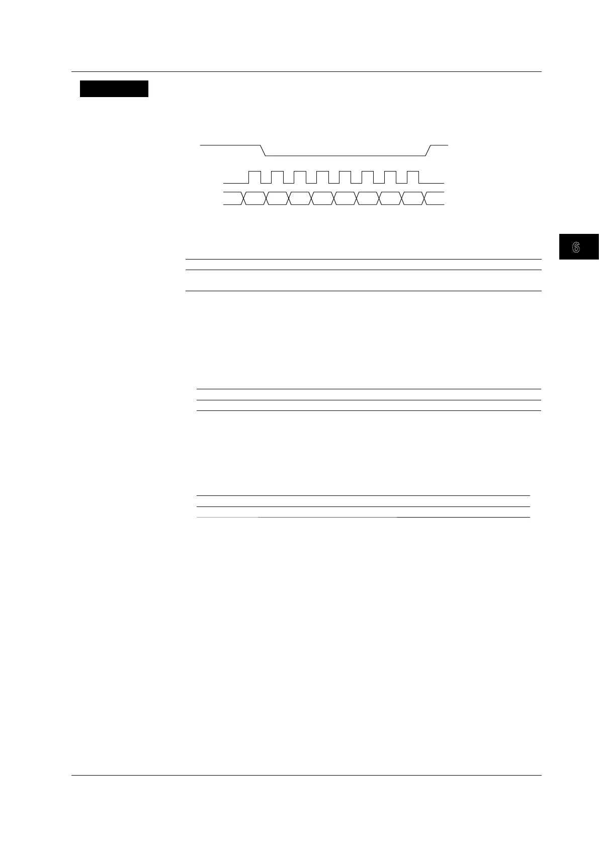
This function triggers on SPI bus signals. The following figure shows the SPI bus signal
timing chart.
Note that the /F5, /F7, or /F8 option is required to analyze SPI bus signals.
Clock
0 1 2 3 4 5 6 (Position)
Data 1
or
Data 2
CS
(Low Active)
Wiring System
Select the wiring system from the following:
Three-wire The DL9000 triggers on the data pattern condition of one data line.
Four-wire The DL9000 triggers on the data pattern conditions of Data 1 and Data 2 lines. You
can also use one of the two data lines as a trigger condition.
Bit Order
You can select the bit order based on the data stream.
• If you are setting the data in binary notation, set the pattern in the order of the data
stream, regardless of the bit order setting.
• If you are setting the data in hexadecimal notation, set the pat
tern in 4-bit segments
according to the bit order setting.
MSB When the data stream is MSB first
LSB When the data stream is LSB first
Data
You can use a data pattern as a trigger condition.
• Comparison Condition
The data trigger condition is met when the result of comparing
the input signal pattern
with the specified pattern meets the selected comparison condition.
True When the patterns match
False When the patterns don’t match
• Comparison Start Position
Set the comparison start position. For example, to start comparing from the first data
byte after the CS signal is activated, specify zero.
Selectable range: 0 to 9999 bytes
•
Data Size
Set how many consecutive data bytes you want to compare.
Selectable range: 1 to 4 bytes
• Data Pattern
Set the data pattern for the specified size in hexadecimal or bi
nary notation.
• If you specify X, the condition is assumed to be met regardless of the corresponding bit
status.
• If a binary pattern contains any Xs, the corresponding hexadecimal display will be “$.”
6.18 Triggering on a SPI Bus Signal

 Loading...


