5-3
IM 04P01B01-01E
Frequently Used Setup Operations (Setting Mode)
5.1 Setting the Input Range
5
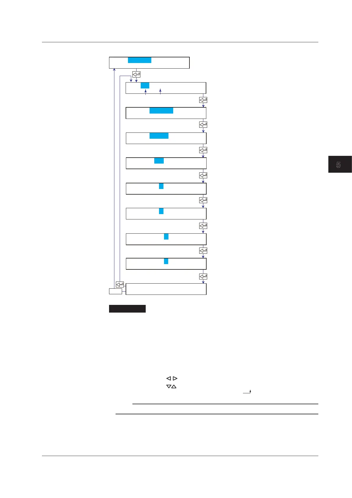
Linear Scaling
Select Scale.
Set the channel range.
Select Volt, TC, RTD, or DI.
Select the range type.
Set the left span value.
Set the right span value.
Set the decimal place
and left scale value.
Set the right scale value.
The new setting takes effect.
First channel Last channel
ESC/?
CH=01-01
Mode=Scale
Type=Volt
Range=2V
Span_L= -2.000
Span_R= 2.000
Scale_L= 0.00
Scale_R= 200.00
01-01 Channel
Description
• Scale Left, Scale Right, and Decimal Place
Selectable range (mantissa): –20000 to 30000
Example: Thevalueintherangeof–100.00to350.00cannotbespecied.The
mantissa of Scale_R is 35000, which exceeds the upper limit of 30000. Set
in the range of –100.0 to 350.0.
Decimal place: XXXXX, XXXX.X, XXX.XX, XX.XXX, X.XXXX
The decimal place is set using Scale_L. It cannot be set using Scale_R.
Example: Change 0.00 to 0.0.
Press the
key to move the cursor to the last digit of 0.00.
Space
Press the key to change the value to 0.0 .
Note
The displayable/printable range of scale values is –19999 to 30000 excluding the decimal.
<Related Topics> Setting the unit: Section 5.3
 Loading...


