3 Product and Functional Description | 3.3 Detectors ZEISS
mation about the topography of the specimen. Surfaces tilted towards the detector provide more
surface detail with brighter edges; specimens tilted away from the detector display shadowing ef-
fects and less surface detail.
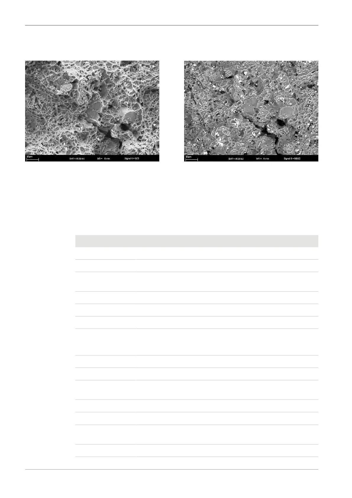
Fig.21: Comparison of topographic contrast – SE/BSE detectors on a fracture surface: SE detector: Image with large
depth of field (left); BSE detector: Good material contrast but with limited topographical detail (right)
Some imaging applications require both, compositional and topographical details. The generation
of mixed SE and BSE images is recommended for such applications. The signal mixing option is
available in the Detectors tab in the SEM Controls panel.
Tilting the specimen increases the signal in the SE detector and sometimes improves the topo-
graphical information. Tilting the specimen towards the SE detector also results in a change of the
solid angle in which both the backscattered and secondary electrons are emitted from the speci-
men.
Parameter Description
Acceleration voltage
0.02kV to 30kV In principle suitable for the entire high-voltage range
1kV to 5kV Low-voltage applications for the compensation of charges and for
surface-sensitive imaging
5kV to 20kV The average voltage range is suitable for many different applications
20kV to 30kV Voltage range frequently used for analytical purposes
Working distance
≥4 mm If the working distance is too short, shadowing effects occur which
diminish the efficiency of the detector. Below 20kV, the SEs are ab-
sorbed by the field of the electrostatic lens
4mm to 6mm For low-voltage applications (1kV to 5kV)
6mm to 12mm Useful for the average voltage range (5kV to 20kV)
12mm to 30mm Recommended only for low magnifications and to increase the depth
of field
Collector voltage
300V Standard value of the collector voltage
0V to 400V Variation of the collector voltage at high magnifications to obtain the
mixed signal
−150V to 0V For pseudo-BSE images
36 Instruction Manual ZEISS EVO | en-US | Rev. 10 | 354706-0780-006