3 Installation
980-001-0210G NetPath 100 User’s Manual - Installation Guide 3-3
June
1999
Connections
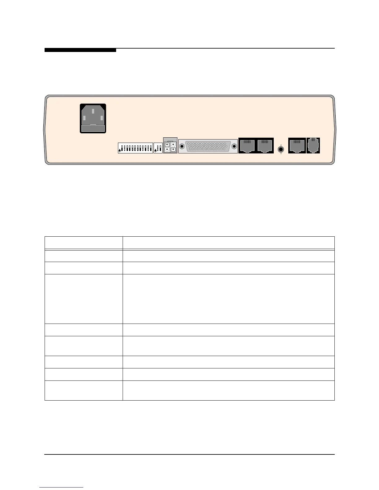
NetPath 100 has connectors on the rear panel for power and input/output connections.
Rear panel connectors and controls are shown and described in Figure 3-10 and
Table 3-1.
Figure 3-10 NetPath 100 Rear Panel (Basic)
DATA PORT
AUX 1 AUX 2
T1
LINE
MODEM
LINE
CONFIGURATION
CONFIG
O
N
12
3
456789101112
O
N
12
FUSE
2A/250V
SLOW BLOW
5x20mm
90-250 VAC
.5A
50-60 Hz
CONTROL
OUTPUT
FOR CONTINUED PROTECTION AGAINST RISK OF FIRE,
REPLACE ONLY WITH SAME TYPE AND RATING OF FUSE.
"CAUTION"
NVM
RESET
Table 3-1 Basic NetPath 100 Input/Output Connectors and Control Specifications
Connectors Description
Power Connector Internal Power Supply with IEC 320 power cord.
Control Output 4-pin keyed connector to control Model 467 Power Control Unit.
Data Port DB-44, high-density connectors provide the following interfaces,
selected by the interface cable used:
EIA-530
EIA-530-A
ITU-V.35
ITU-X.21-NS (Non-Switched)
AUX 1, AUX 2 8-pin modular connectors, EIA-232
NVM Reset/Config Recessed push button that causes the unit’s NVM to be cleared if pressed and held
(approximately four seconds) during the unit’s power-up self-test.
T1 Line 8-pin modular connector, RJ48C
Modem Line (Analog) 6-pin modular connector, RJ11C
DIP Switches One 2-position and one 12-position DIP switch for the initial setting of the DLCI
address, the DS0 configuration for the T1 link, and the CSU/DTE parameters.