3 Installation
3-6 NetPath 100 User’s Manual - Installation Guide 980-001-0210G
June
1999
Optional Power
Control Unit Power
Connection
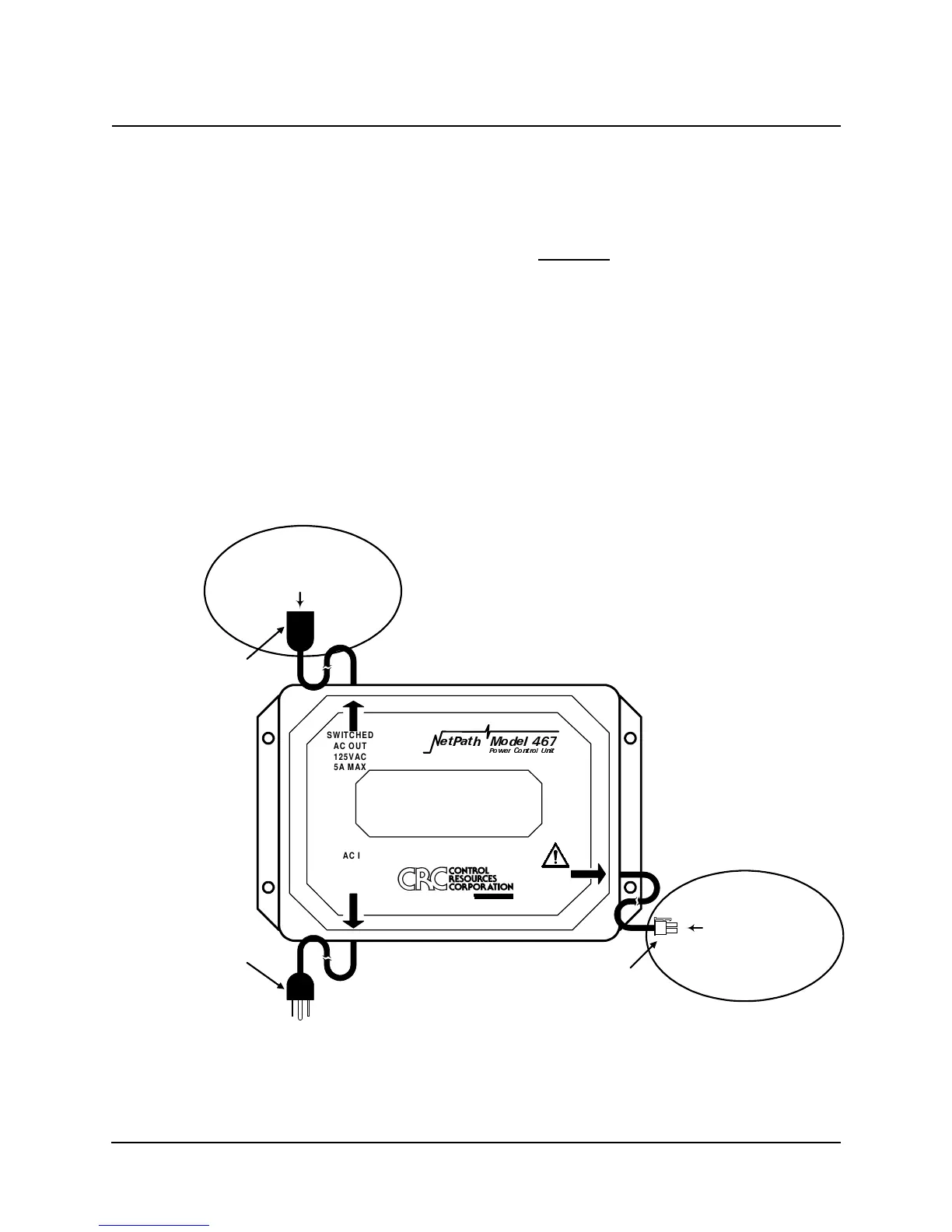
Three connections are required to install an optional Model 467 Power Control Unit.
A. Connect the device to be controlled (usually the DTE connected to the NetPath
100) to the Switched AC OUT Socket (125 VAC) of the Power Control Unit
shown in Figure 3-12 below.
CAUTION
Do not plu
the power cord from the NetPath 100 into the
AC OUT socket of the Power Control Unit. This is an
invalid confi
uration.
B. Connect the Power/Control Cable from the Power Control Unit shown in Figure 3-
12 to the Control Output connector on the rear panel of the NetPath 100 (shown in
Figure 3-11).
C. Verify that the proper voltage is present at the outlet to be used (90 - 125 VAC,
50 - 60 Hz). If the outlet voltage is correct, plug the AC IN Plug from the Power
Control Unit into the AC outlet.
Fi
ure 3-12 Power Control Unit Connections
Continue the installation by making Input/Output connections and Configuring the
NetPath 100 as described in the following sections of this manual.
SEE
USERS
MANUAL
HW3DWK 0RGHO
3RZHU &RQWURO 8QLW
SWITCHED
AC OUT
125VAC
5A MAX
AC IN
125VAC
5.5 AMPS MAX
50-60Hz
A P-COM Compan
WARNING!
NO USER SERVICEABLE PARTS INSIDE
HIGH INTERNAL VOLTAGES PRESENT
INTERNAL SHOCK HAZARD PRESENT
AC IN
Plu
AC OUT
Socket
Power/Control
Connector
4-Pin, Ke
ed, Lockin
Connect DTE AC In
ut
here for
NetPath Controlled Power
Connect to
Control Out
ut Connector
on NetPath 100 rear
anel