3 Installation
980-001-0210G NetPath 100 User’s Manual - Installation Guide 3-11
June
1999
EIA-530-A Adapter
Cable
Use CRC cable assembly # 135-003-0400, or per pinout shown in Table 3-6.
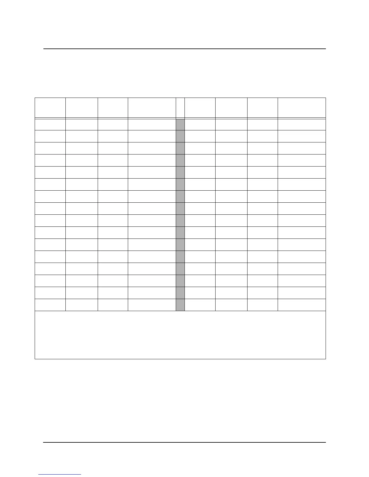
Table 3-6 EIA-530-A Interface Adapter Cable (CBC=3)
DB-25F
Pin
DB-44M
Pin
Si
nal Direction
DB-25F
Pin
DB-44M
Pin
Si
nal Direction
116ShieldN/A 14 32 TD-B Input
2 17 TD-A Input 15 25 TC-A Output
3 18 RD-A Output
16 33 RD-B Output
4 19 RTS-A Input
17 27 RC-A Output
520CTS-AOutput 18
6 6 DSR(s) Output
19 34 RTS-B Input
7 22 Sig. Gnd. N/A
20 9 DTR(s) Input
823DCD-AOutput 21
9 42 RC-B Output
22
10 38 DCD-B Output
23
11 44 TCE-B Input 24 29 TCE-A Input
12 40 TC-B Output
25
13 35 CTS-B Output
26 CBC-A* N/A
28 CBC-B* N/A
30 to 22 CBC-C* N/A
Notes: *CBC = Cable Code pin.
(s) = single ended.
Twisted Pair cable conductors for: TD-A & B, RD-A & B, RTS-A & B, CTS-A & B,
DCD-A & B, TC-A & B, RC-A & B and TCE-A & B.
Install 470 Ohm resistor at DB-44 end across pins: 9 to 37.
Shielded cable is recommended.