Application macros 115
PID control macro
This macro provides parameter settings for closed-loop control systems such as
pressure control, flow control, etc. Control can also be switched to speed control
using a digital input. To enable the macro, set the value of parameter 9902 APPLIC
MACRO to 6 (PID CONTROL).
For the parameter default values, see section Default values with different macros on
page 180. If you use other than the default connections presented below, see section
I/O terminals on page 53.
Note: The default I/O connections described below are applicable to firmware version
5.050 or later. For the default values in earlier firmware versions, see Revision A of
this user’s manual.
Note: Parameter 2108 START INHIBIT must remain in the default setting 0 (OFF).
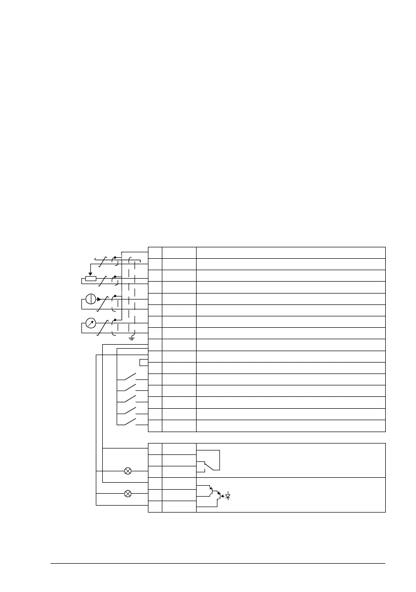
Default I/O connections
X1A
1 SCR Signal cable shield (screen)
2AI1 Proc. ref. (PID) / Motor freq. ref. (Hand): 0…10 V
1)
3 GND Analog input circuit common
4 +10V Reference voltage: +10 V DC, max. 10 mA
5AI2 Process actual value: 4…20 mA
3)
6 GND Analog input circuit common
7AO Motor speed value: 0…20 mA
8 GND Analog output circuit common
9 +24V Auxiliary voltage output: +24 V DC, max. 200 mA
10 GND Auxiliary voltage output common
11 DCOM Digital input common
12 DI1 Stop (0) / Start (1) (PID)
13 DI2 PID (0) / Hand (1) control selection
14 DI3 Constant speed 1: parameter 1202
15 DI4 Run enable
16 DI5 Stop (0) / Start (1) (Hand)
X1B
17 ROCOM Relay output 1
No fault [Fault (-1)]
18 RONC
19 RONO
20 DOSRC Digital output, max. 100 mA
No fault [Fault (-1)]
21 DOOUT
22 DOGND
max. 500 ohm
1…10 kohm
2)
1)
Hand: 0…10 V -> speed reference.
PID: 0…10 V -> 0…100% PID setpoint.
2)
360 degree grounding under a clamp.
3)
The signal source is powered externally. See the
manufacturer’s instructions. To use sensors
supplied by the drive aux. voltage output, see page
55.
Tightening torque: 0.4 N·m / 3.5 lbf·in.
Safe torque off connections (X1C:STO; not shown in
the diagram) are jumpered by default.

 Loading...


