236 Actual signals and parameters
COMM Defines bit 13 of Command word 1 as the control for forcing
the speed to zero. The Command word 1 is supplied
through fieldbus communication (parameter 0301).
7
DI1(INV) Inverted digital input DI1. Defines inverted digital input
DI1
as the control for forcing the speed to zero.
• De-activating the digital input forces the speed to zero.
• Activating the digital input: speed control resumes normal
operation.
-1
DI2(INV) See selection DI1(INV).-2
DI3(INV) See selection DI1(INV).-3
DI4(INV) See selection DI1(INV).-4
DI5(INV) See selection DI1(INV).-5
23 SPEED
CONTROL
Speed controller variables. See section Speed controller
tuning on page 144.
Note: These parameters do not affect drive operation in
scalar control, ie, when parameter 9904 MOTOR CTRL
MODE setting is SCALAR: FREQ.
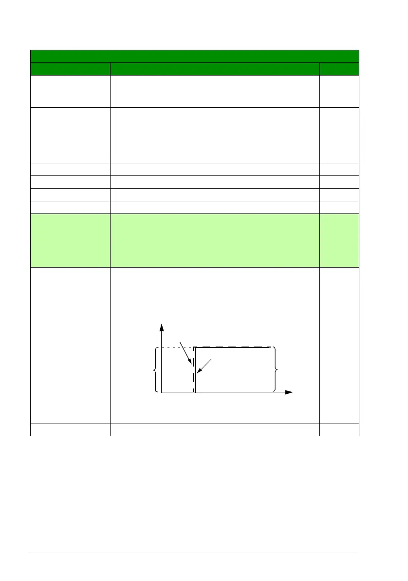
2301 PROP GAIN Defines a relative gain for the speed controller. High gain
may cause speed oscillation.
The figure below shows the speed controller output after an
error step when the error remains constant.
Note: For automatic setting of the gain, use autotune run
(parameter 2305 AUTOTUNE RUN).
5.00
0.00…200.00 Gain 1 = 0.01
All parameters
No. Name/Value Description Def/FbEq
Gain = K
p
= 1
T
I
= Integration time = 0
T
D
= Derivation time = 0
Controller
output =
K
p
·e
e = Error
value
Error
value
Controller output
%
t

 Loading...


