408 Appendix: Resistor braking
Placing the brake resistor
Install all resistors in a place where they will cool.
WARNING! The materials near the brake resistor must be non-flammable. The
surface temperature of the resistor is high. Air flowing from the resistor is of
hundreds of degrees Celsius. Protect the resistor against contact.
Protecting the system in brake circuit fault situations
Protecting the system in cable and brake resistor short-circuit situations
For short-circuit protection of the brake resistor connection, see Brake resistor
connection on page 388. Alternatively, a two-conductor shielded cable with the same
cross-sectional area can be used.
Protecting the system in brake resistor overheating situations
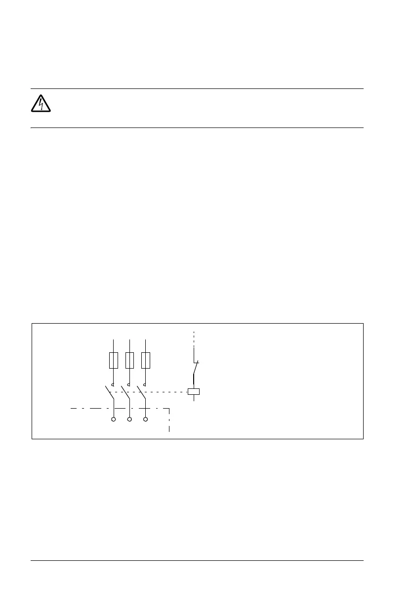
The following setup is essential for safety – it interrupts the main supply in fault
situations involving chopper shorts:
• Equip the drive with a main contactor.
• Wire the contactor so that it opens if the resistor thermal switch opens (an
overheated resistor opens the contactor).
Below is a simple wiring diagram example.
Electrical installation
For the brake resistor connections, see the power connection diagram of the drive on
page 51.
U1 V1 W1
L1 L2 L3
1
2
3
4
5
6
K1
Q
Thermal switch of the resistor
ACS355
Fuses

 Loading...


