1/1/1
0/1/1
1/1/0
1/1/0
1)
2)
3)
4)
7)
8)
5)
0/0/1
9)
6)
A
A
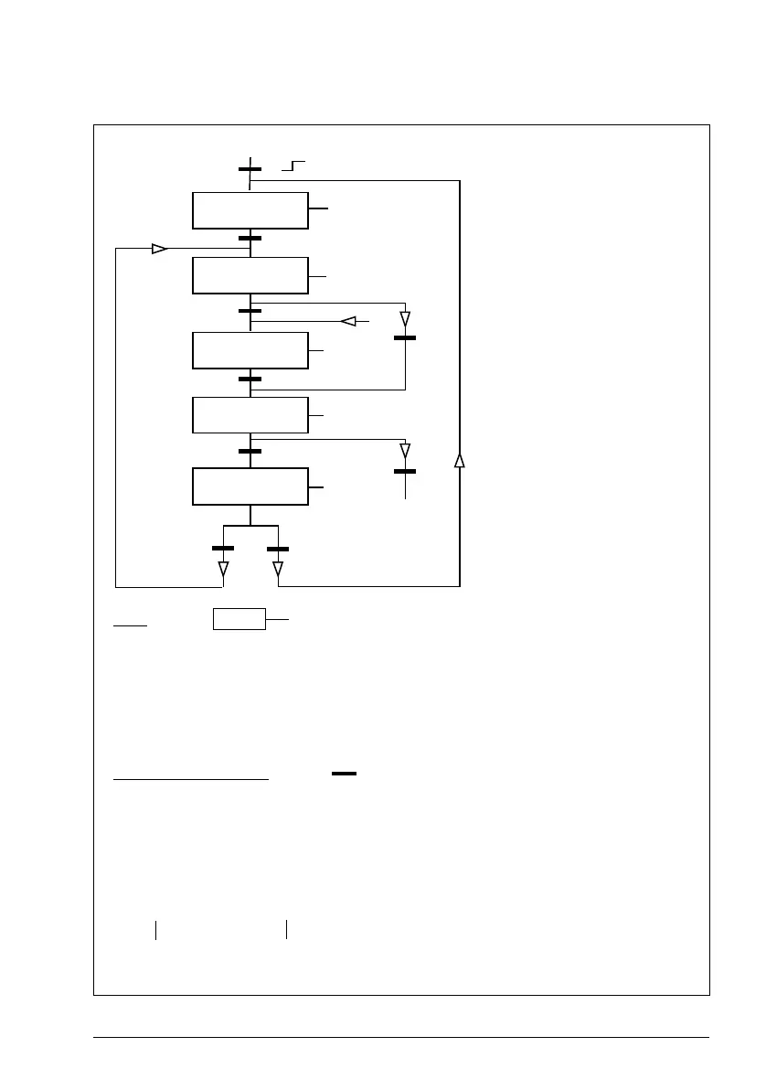
State (Symbol )
- NN: State name
- X/Y/Z: State outputs/operations
X = 1 Open the brake. The relay output set to brake on/off control energizes.
Y = 1 Forced start. The function keeps the internal Start on until the brake is closed in
spite of the status of the external Start signal.
Z = 1 Ramp in zero. Forces the used speed reference (internal) to zero along a ramp.
State change conditions (Symbol )
1) Brake control active 0 -> 1 OR Inverter is modulating = 0
2) Motor magnetised = 1 AND Drive running = 1
3) Brake is open AND Brake open delay passed AND Start = 1
4) Start = 0
5) Start = 0
6) Start = 1
7) Actual motor speed < Brake close speed AND Start = 0
8) Start = 1
9) Brake is closed AND Brake close delay passed = 1 AND Start = 0
RFG = Ramp function
generator in the speed control
loop (reference handling).
NO
MODULATION
RELEASE RFG
INPUT
OPEN
BRAKE
RFG INPUT
TO ZERO
CLOSE
BRAKE
From any state
(rising edge)

 Loading...


