152 Program features
Process controller PID1
PID1 has two separate sets of parameters (40 PROCESS PID SET 1, 41 PROCESS
PID SET 2). Selection between parameter sets 1 and 2 is defined by a parameter.
In most cases when there is only one transducer signal wired to the drive, only
parameter set 1 is needed. Two different parameter sets (1 and 2) are used, eg, when
the load of the motor changes considerably in time.
External/Trim controller PID2
PID2 (42 EXT / TRIM PID) can be used in two different ways:
• External controller: Instead of using additional PID controller hardware, the user
can connect PID2 output through drive analog output or fieldbus controller to
control a field instrument like a damper or a valve.
• Trim controller: PID2 can be used to trim or fine tune the reference of the drive.
See section Reference trimming on page 130.
Block diagrams
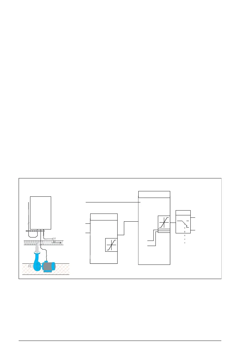
The figure below shows an application example: The controller adjusts the speed of a
pressure boost pump according to the measured pressure and the set pressure
reference.
ref
k
ti
td
i
dFiltT
errVInv
oh1
ol1
Speed
reference
%ref = 4010
…
.
.
.
AC T PA R FU NC DR IVE
E NT ER
LO C
RE M
RE SET
RE F
A C S 6 0 0
0 . . . 1 0 b a r
4 . . . 2 0 m A
3
3
2
PID control block diagramExample:
Pressure boost pump
4001
4002
4003
4004
4005
PIDmin
PIDmax
4014
4021
AI1
AI2
IMOT
%ref
Actual values
PID
Switch
9904 = 0
Frequency
reference

 Loading...


