Electrical installation 53
Connecting the control cables
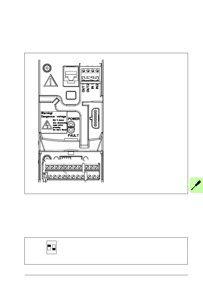
I/O terminals
The figure below shows the I/O terminals. Tightening torque is 0.4 N·m / 3.5 lbf·in.
Voltage and current selection for analog inputs
Switch S1 selects voltage (0 [2]…10 V / -10…10 V) or current (0 [4]…20 mA /
-20…20 mA) as the signal types for analog inputs AI1 and AI2. The factory settings
are unipolar voltage for AI1 (0 [2]…10 V) and unipolar current for AI2 (0 [4]…20 mA),
which correspond to the default usage in the application macros. The switch is
located to the left of I/O terminal 9 (see the I/O terminal figure above).
X1A:
1: SCR
2: AI1
3: GND
4: +10 V
5: AI2
6: GND
7: AO
8: GND
9: +24 V
10: GND
11: DCOM
12: DI1
13: DI2
14: DI3
15: DI4
16: DI5 digital or frequency input
X1B:
17: ROCOM
18: RONC
19: RONO
20: DOSRC
21: DOOUT
22: DOGND
X1C:STO
1: OUT1
2: OUT2
3: IN1
4: IN2
mA
V
S1
X1A
X1B
AI1
AI2
S1: Selects voltage or current as
the signal types for analog
inputs AI1 and AI2.
9 10 11 12 13 14 15 16 20 21 22
1 2 3 4 5 6 7 8 17 18 19
X1C:STO
1 2 3 4
AI1
AI2
Top position (ON): I (0 [4]…20 mA, default for AI2; or -20…20 mA)
Bottom position (OFF): U (0 [2]…10 V, default for AI1; or -10…10 V)
S1
ON
21

 Loading...


