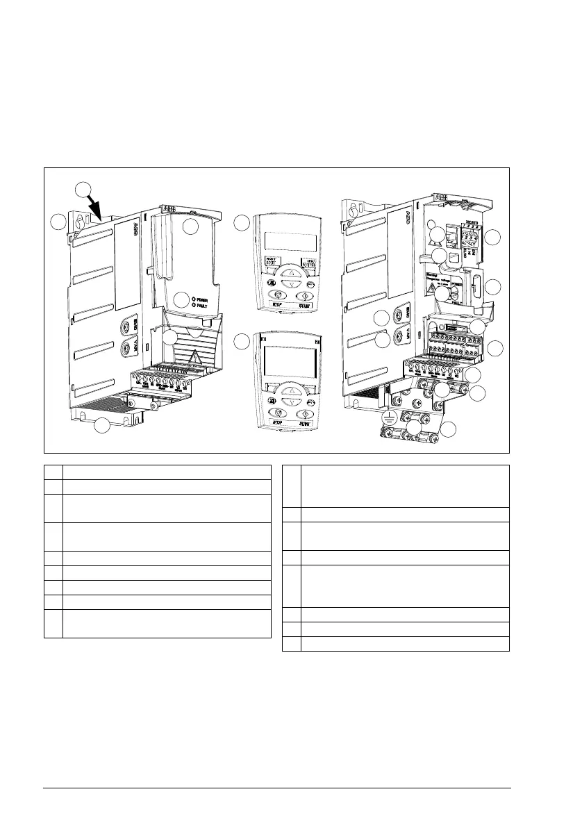
1 Cooling outlet through top cover
2 Mounting holes
3 Panel cover (a) / basic control panel (b) /
assistant control panel (c)
4 Terminal cover (or optional potentiometer
unit MPOT-01)
5 Panel connection
6 Option connection
7 STO (Safe torque off) connection
8 FlashDrop connection
9 Power OK and Fault LEDs. See section
LEDs on page 372.
10 EMC filter grounding screw (EMC).
Note: The screw is on the front in frame
size R4.
11 Varistor grounding screw (VAR)
12 Fieldbus adapter (serial communication)
connection
13 I/O connections
14 Input power connection (U1, V1, W1),
brake resistor connection (BRK+, BRK-)
and motor connection (U2, V2, W2).
15 I/O clamping plate
16 Clamping plate
17 Clamps
2
4
3b
3a
3c
7
8
8
14
2
12
11
10
9
16
17
17
1
13
15
Covers on (R0 and R1) Covers off (R0 and R1)
5
6

 Loading...


