Appendix: Extension modules 413
Note: The signal and power connections to the drive are automatically made through
a 6-pin connector.
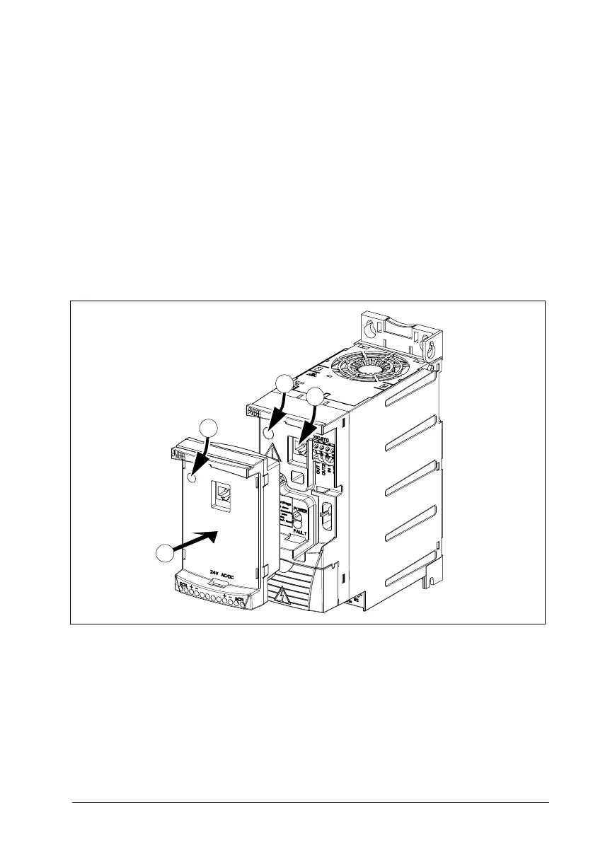
6. Ground the extension module by inserting the screw removed from the drive in
the top left corner of the extension module. Tighten the screw using a torque of
0.8 N·m (7 lbf·in).
Note: Correct insertion and tightening of the screw is essential for fulfilling the EMC
requirements and proper operation of the extension module.
7. Install the control panel or panel cover on the extension module.
8. Electrical installation is module-specific. For MPOW-01, see section Electrical
installation on page 415. For MTAC-01, see MTAC-01 pulse encoder interface
module user’s manual (3AFE68591091 [English]), and for MREL-01, see
MREL-01 output relay module user’s manual (3AUA0000035957 [English]).

 Loading...


